Week 3 – Hello new design, goodbye Legos

Hello again,

Team Petri-FI has had an exciting week this week. We have a new design, and we’ve completed and tested a prototype, all in the span of two days! But first, we had some challenges.

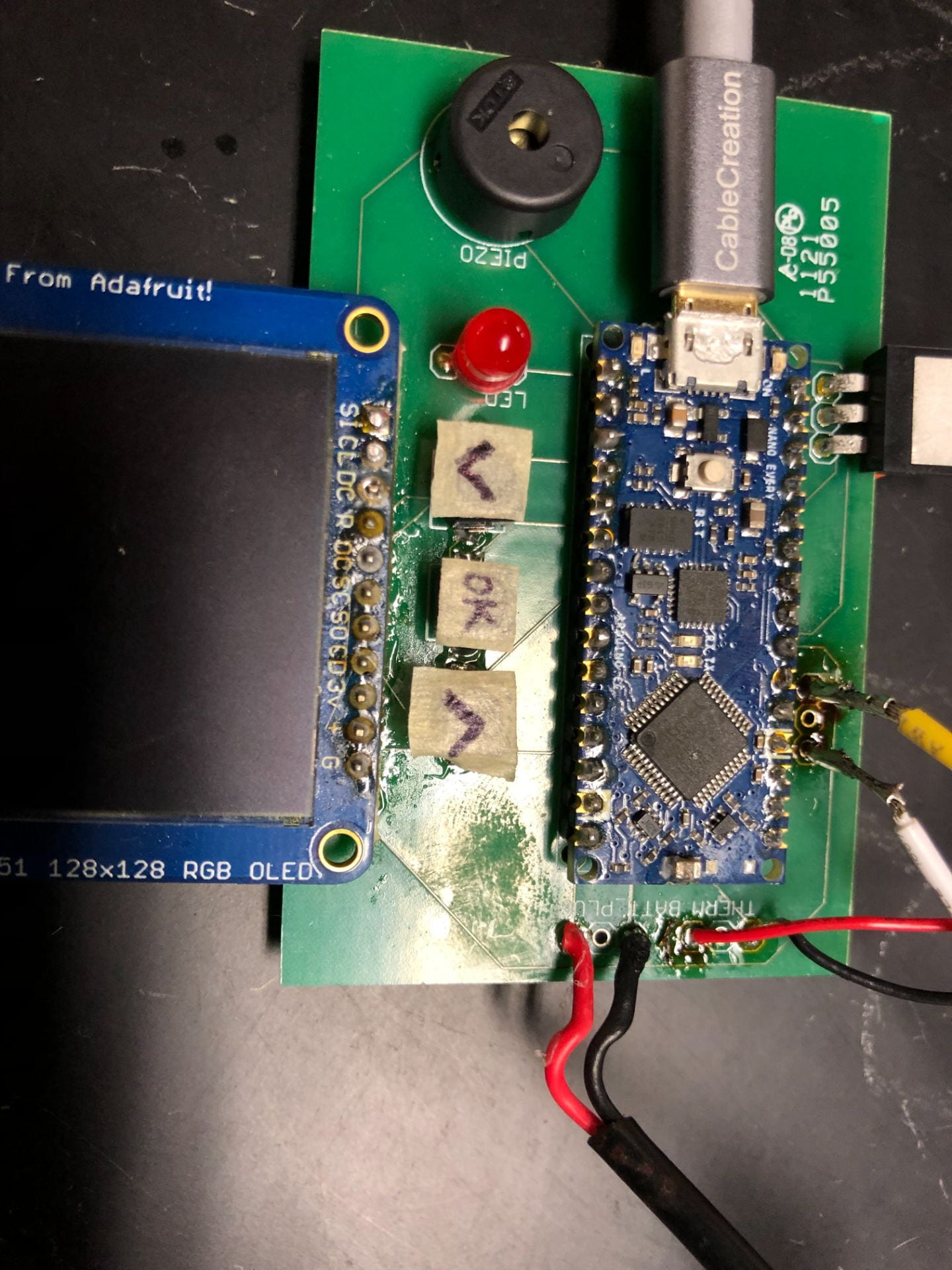
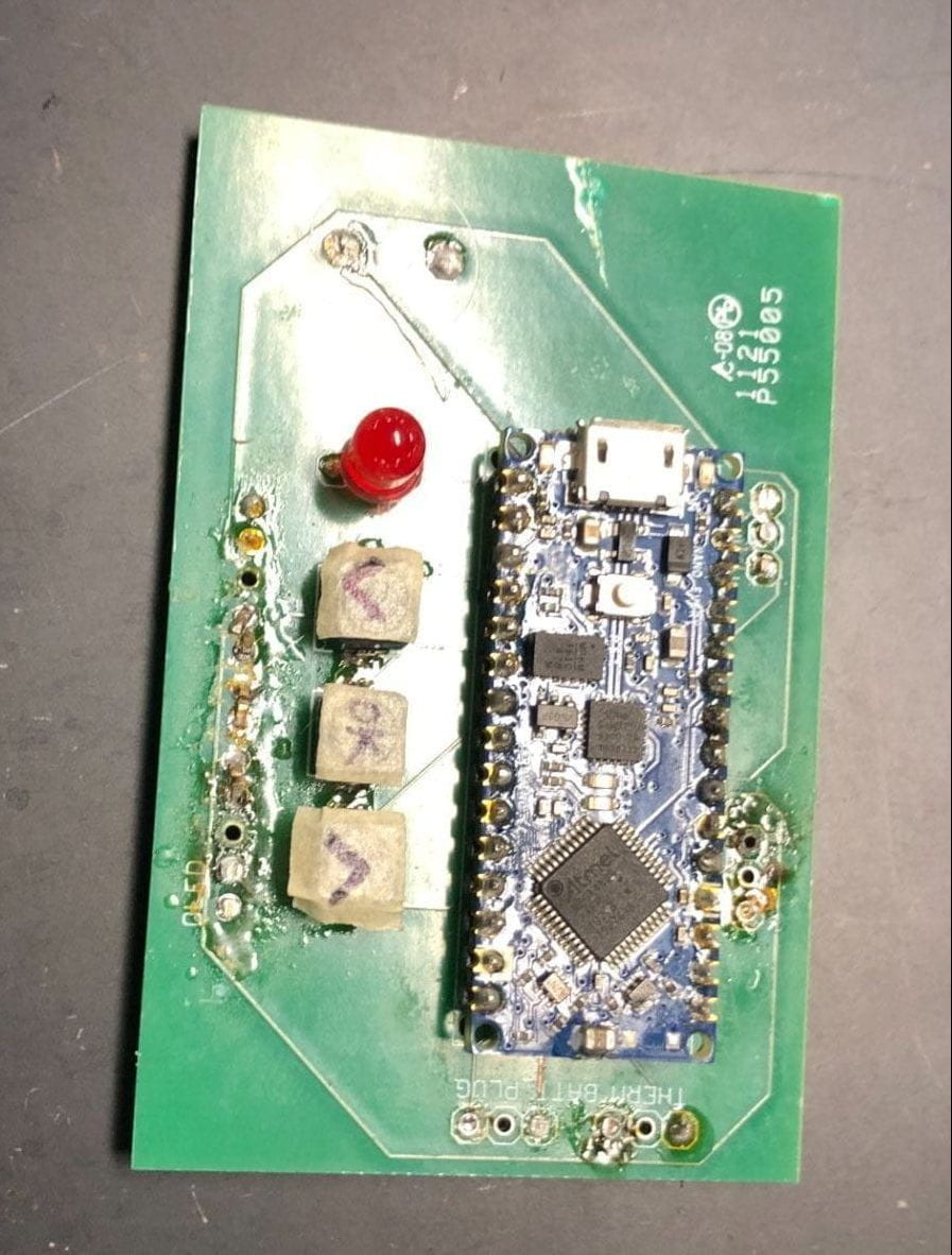
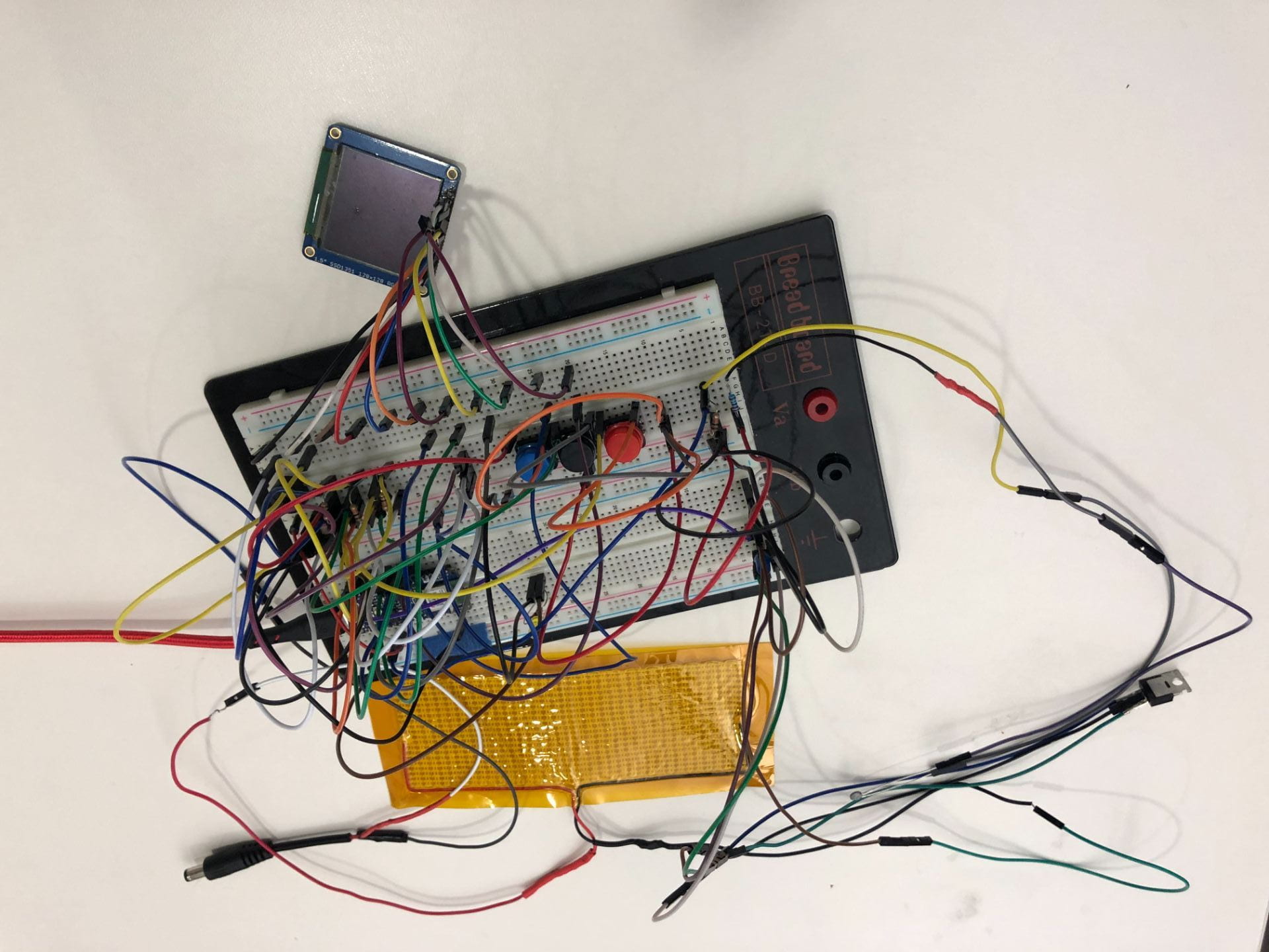
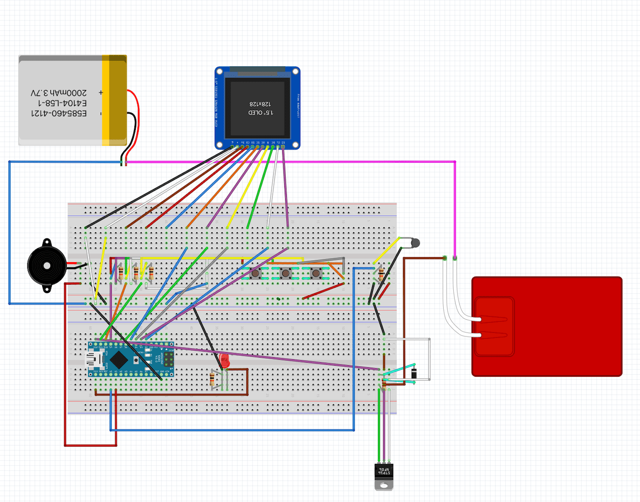
In the last blog post, I talked about creating a breadboard to replace our fried PCB and left it with the ominous words, “Now, to debug it . . .” Debugging has not come easy, but we were fortunate enough to meet with multiple mentors who taught us a lot about electronics. The debugging is still in progress, but in the meantime we’ve built a small circuit for the purpose of heating the heating pads.

Now onto the exciting stuff: our new designs!

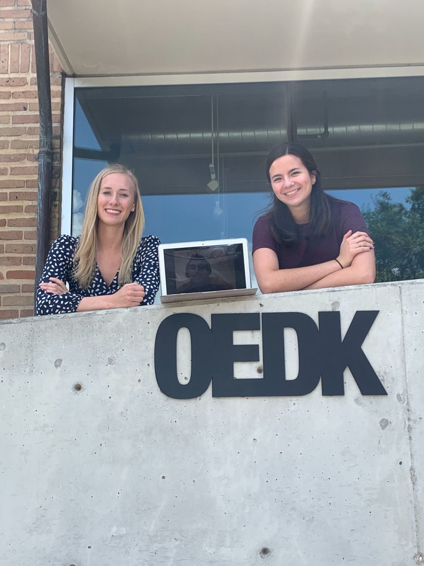
On Thursday, we presented our prototype ideas to Dr. Wettergreen, a professor at the OEDK who’s pretty much the expert on prototyping at Rice. We had two ideas for the heating chamber we would use: a double-walled thermos and a lunchbox. Dr. Wettergreen pointed out something that we hadn’t thought of: while both are open source in the sense that anyone can go online and order a thermos or lunchbox of similar size, they’re proprietary – you would need to order from a company, wait for shipping, etc. Why not just make your own box?

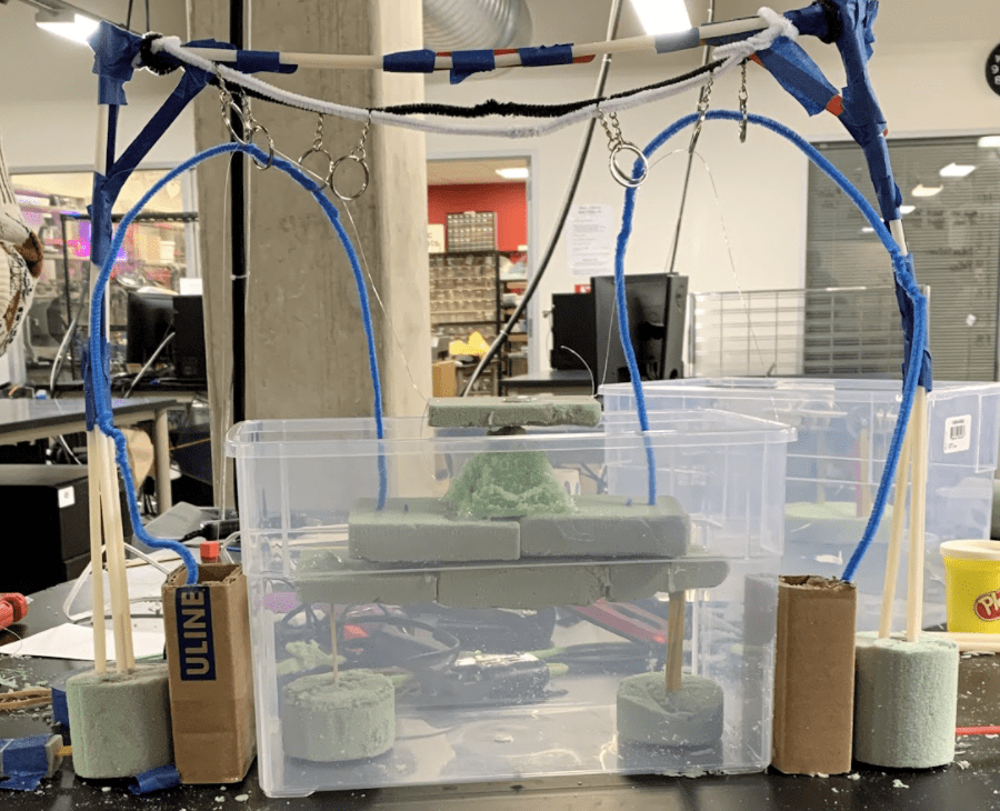
We started out with the “pink box.”

The aptly named “pink box.”

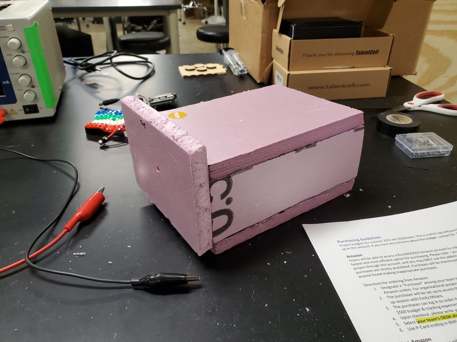
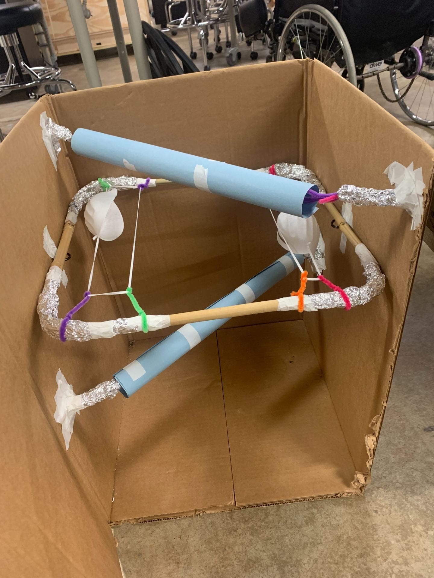
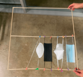
It’s made entirely out of polyiso insulation, and the inside contains the heating apparatus. The heating pad is inside on the bottom, and above that, perched atop a platform made of Legos, are the petrifilms. For this iteration, we wired up a breadboard externally, just so we could easily control our device as we began initial heat testing.

Just starting to heat.
Finished.

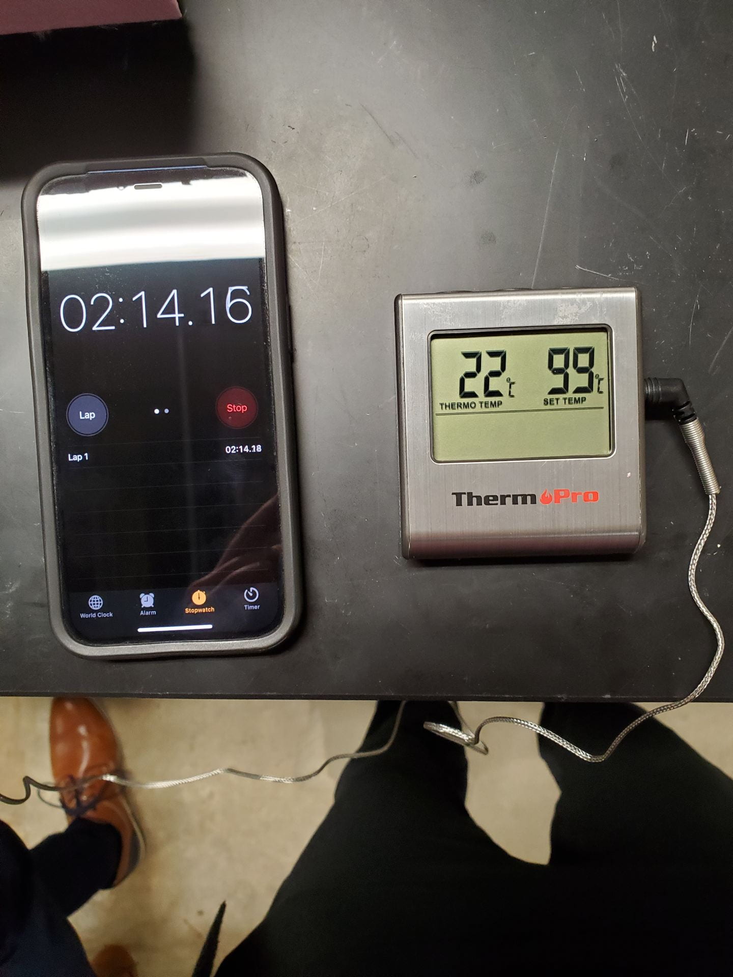
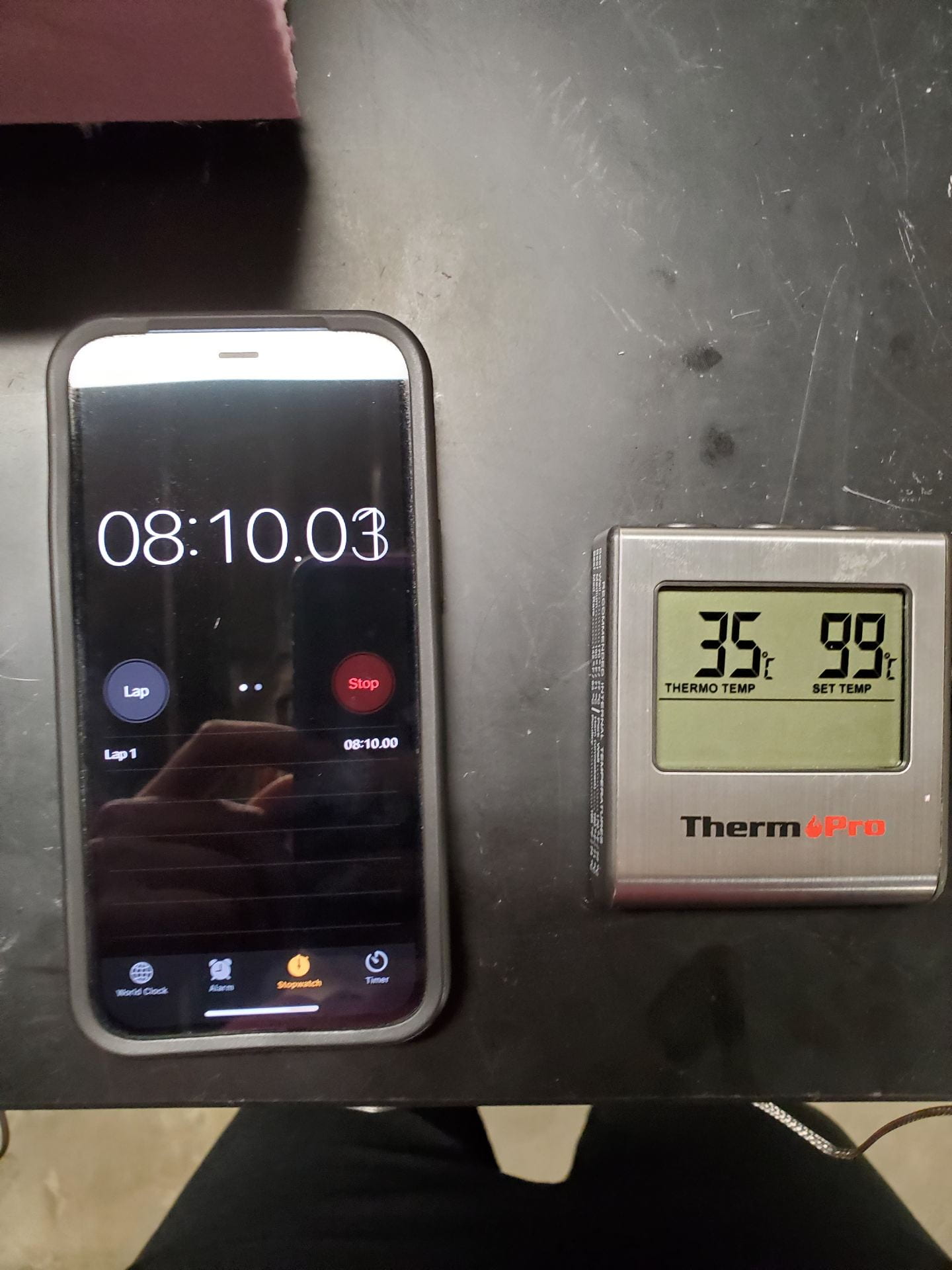
Our data came out quite nicely – it only took seven and a half minutes to heat up from the frigid 20C of the OEDK basement to our target of 35C, and longer to go back down to 20C – 13 minutes. These are quite promising results.

After this test, we ran another one – maximum heating. There’s a legitimate reason for this: when the temperature remains constant, that’s the equilibrium point – the point where the amount of heat going in equals the amount of heat flowing out.

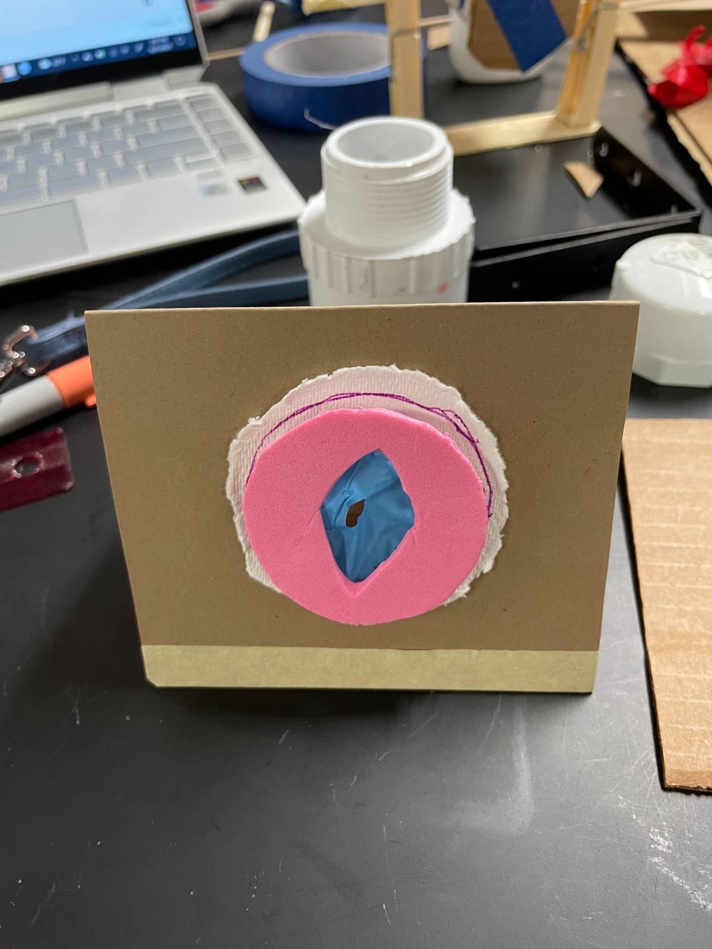
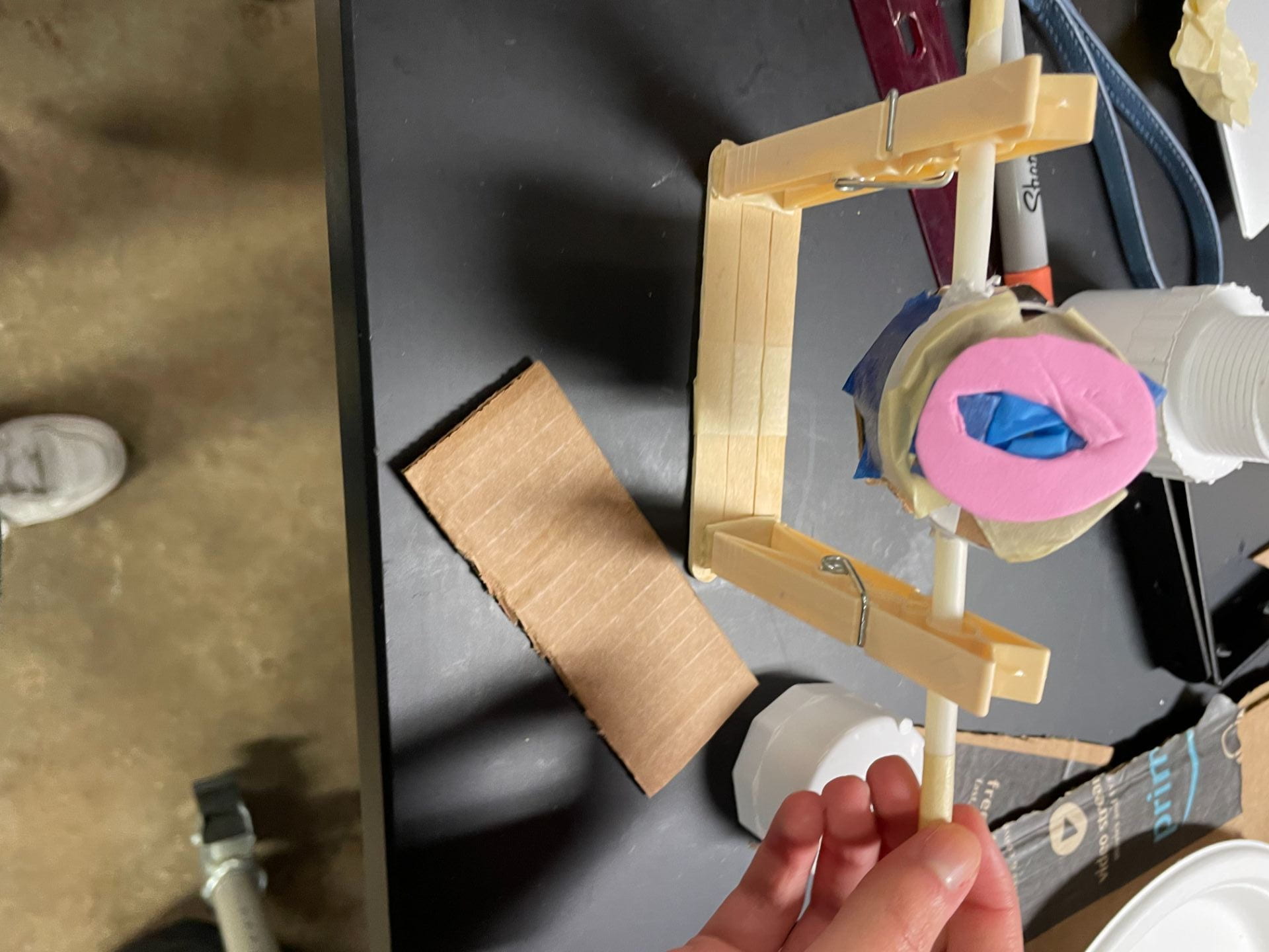
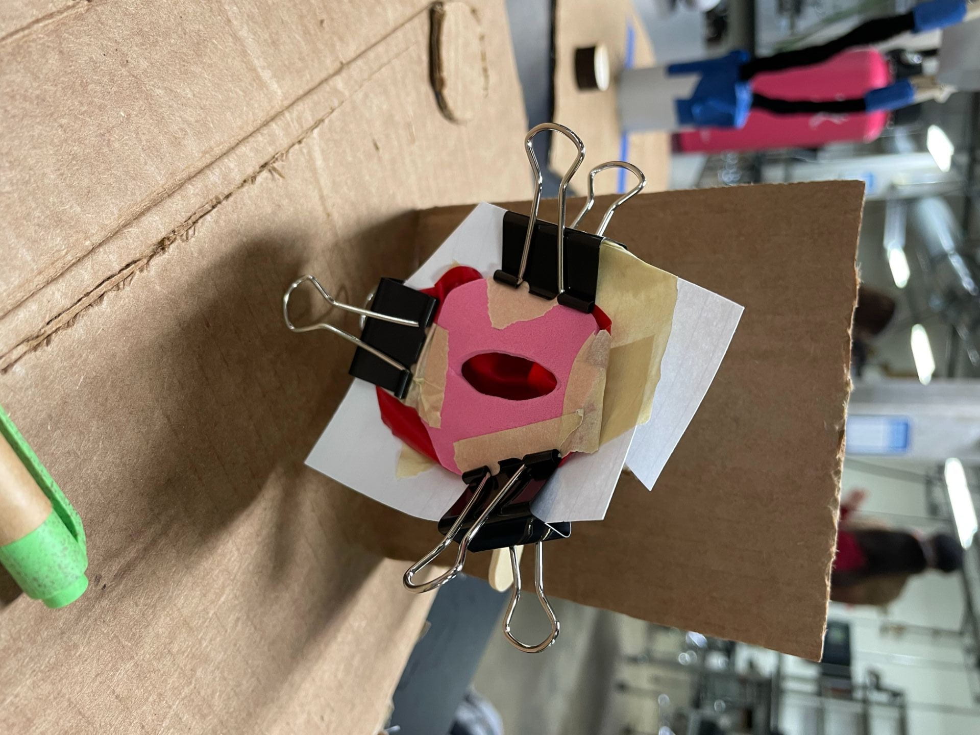
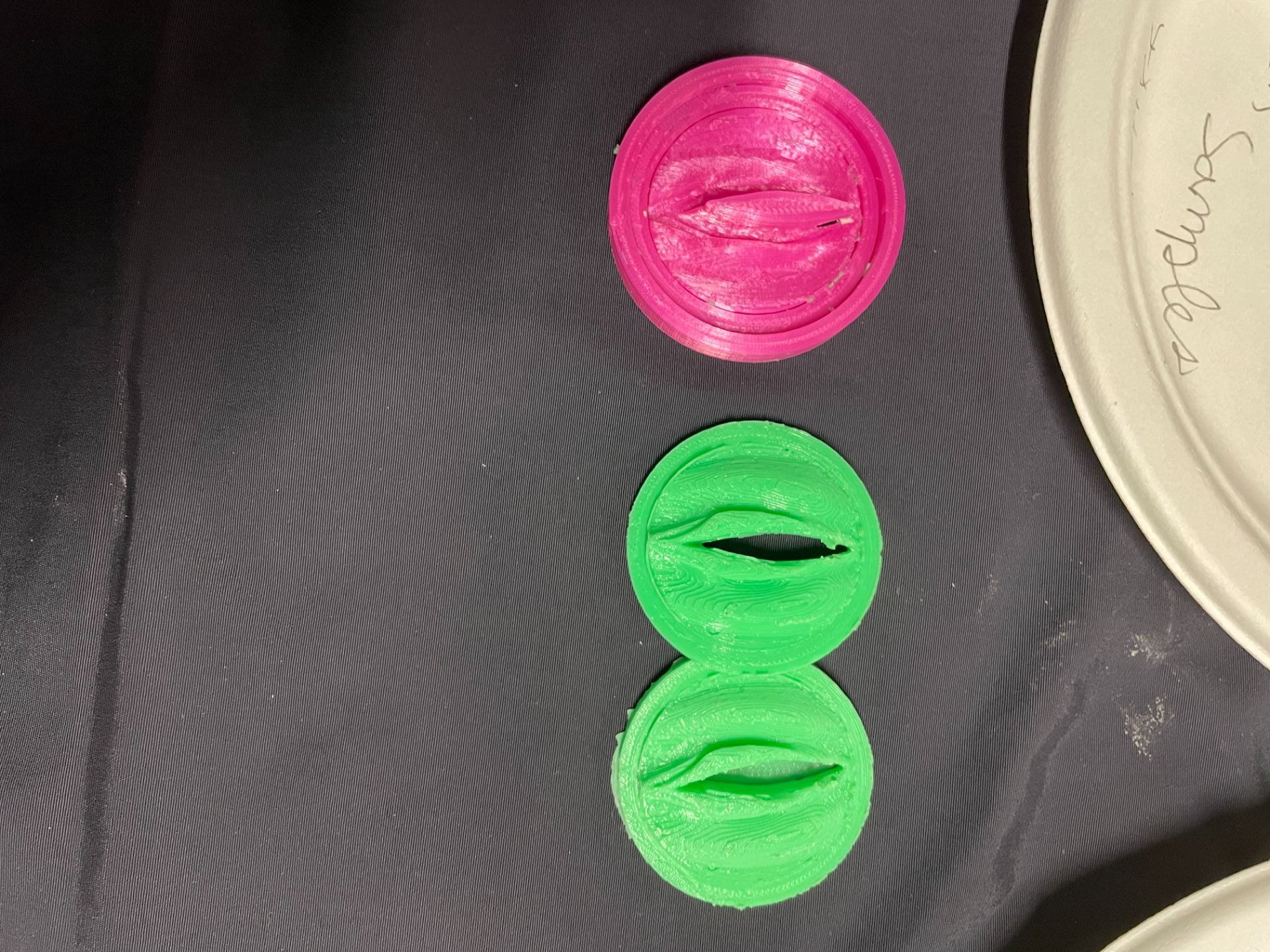
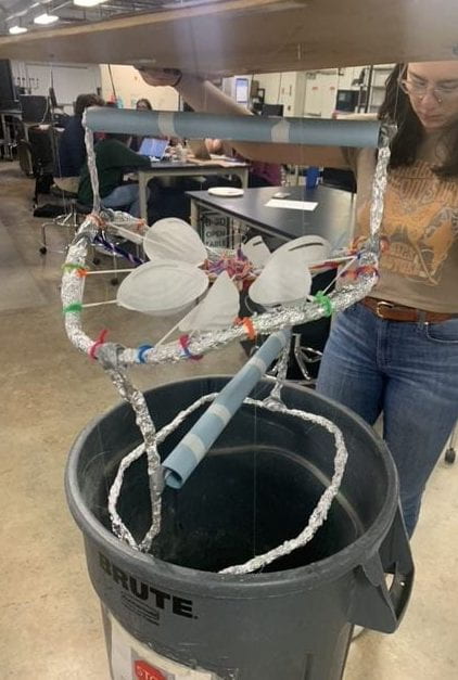
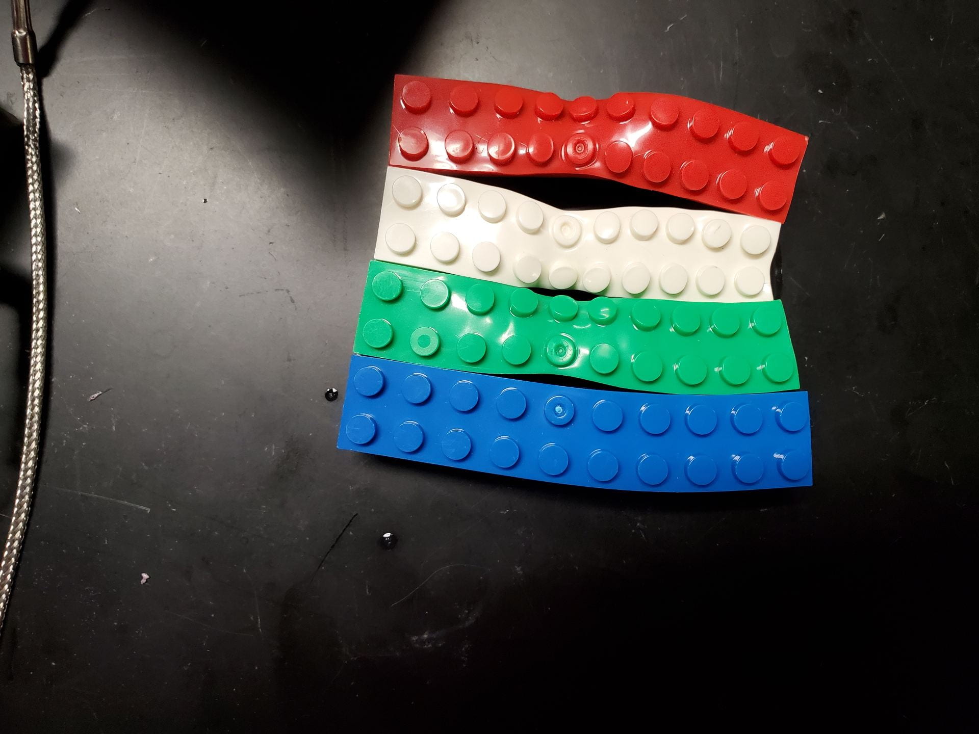
At this point, we can determine the heat loss in our device. (Honestly, though, we mostly just cranked the heat up to see how far it would go). It got up to 66C (150F)! And check out what it did to our makeshift petrifilm holder:

The legos melted. Poor Legos.

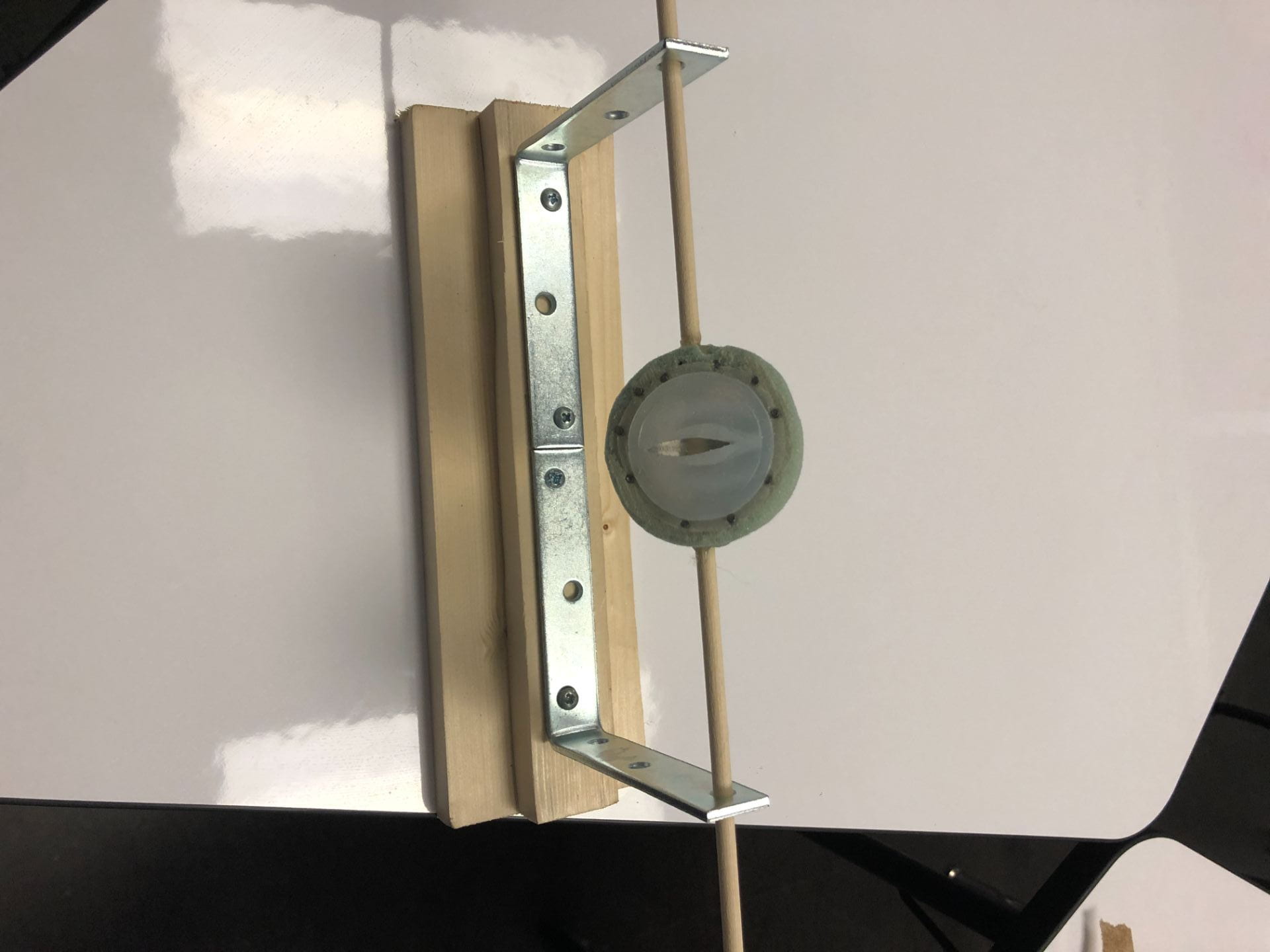
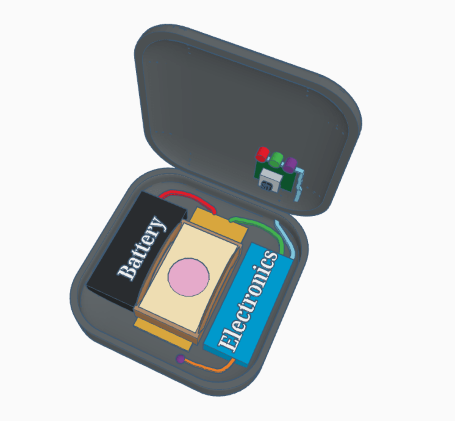
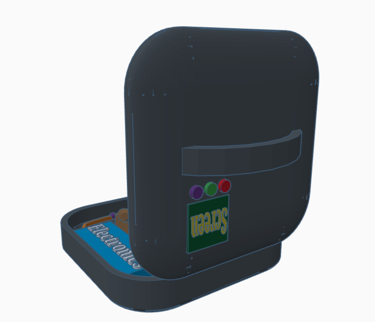
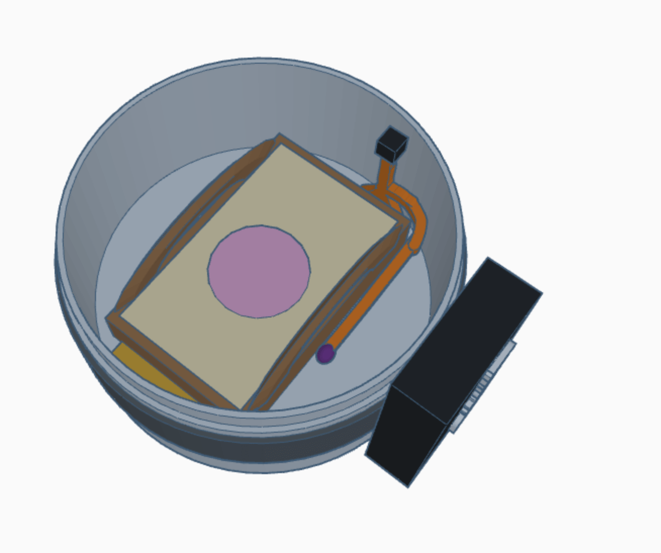
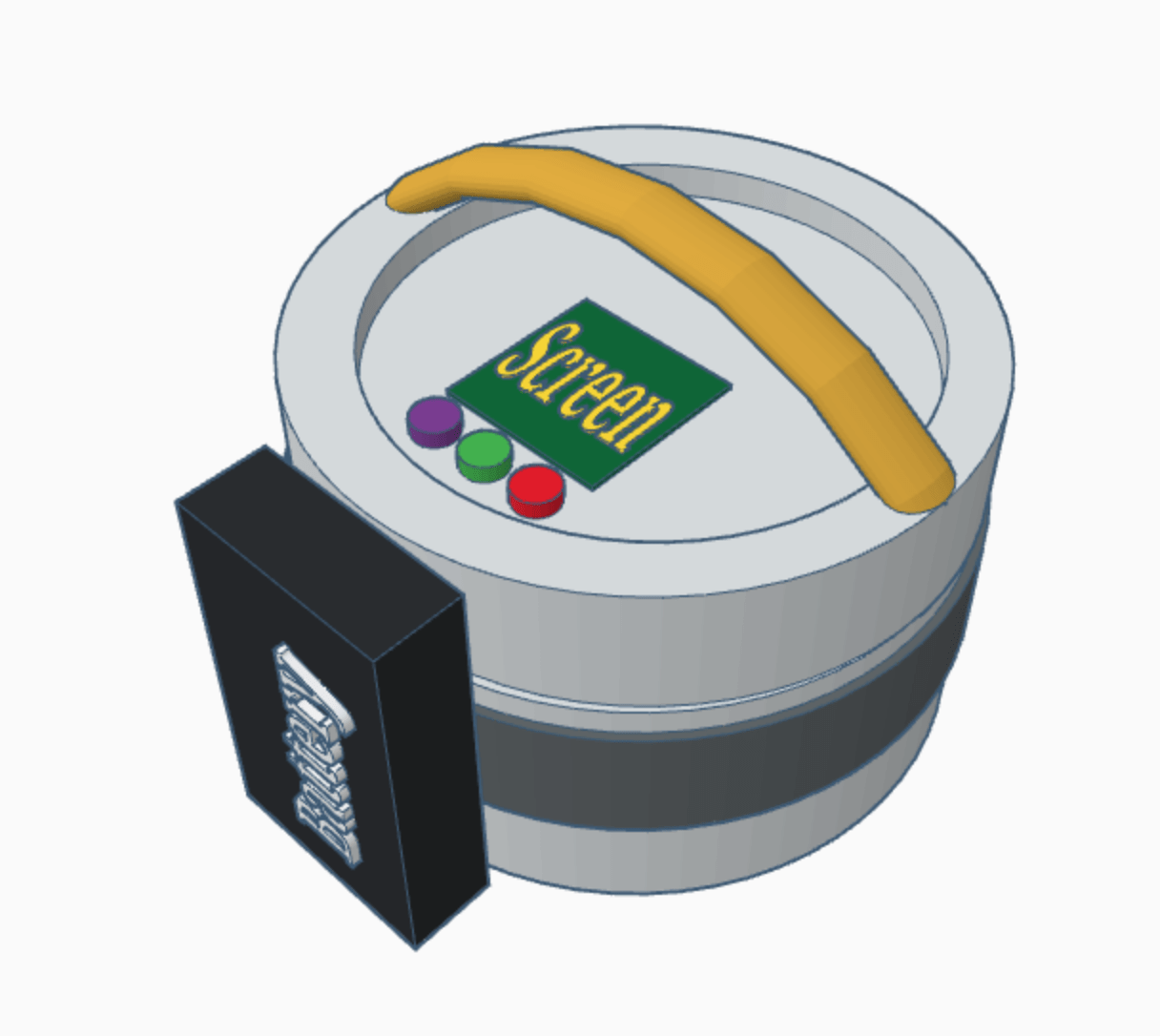
Once we determined that our device does, in fact, get hot, we planned to make something a bit more high-fidelity (i.e. not made of Legos – Legos are cool, but would you buy a piece of lab equipment made out of Legos?). The result was this two-chamber, laser cut wood box:

Two chambered box - outside.Two-chambered box - inside.

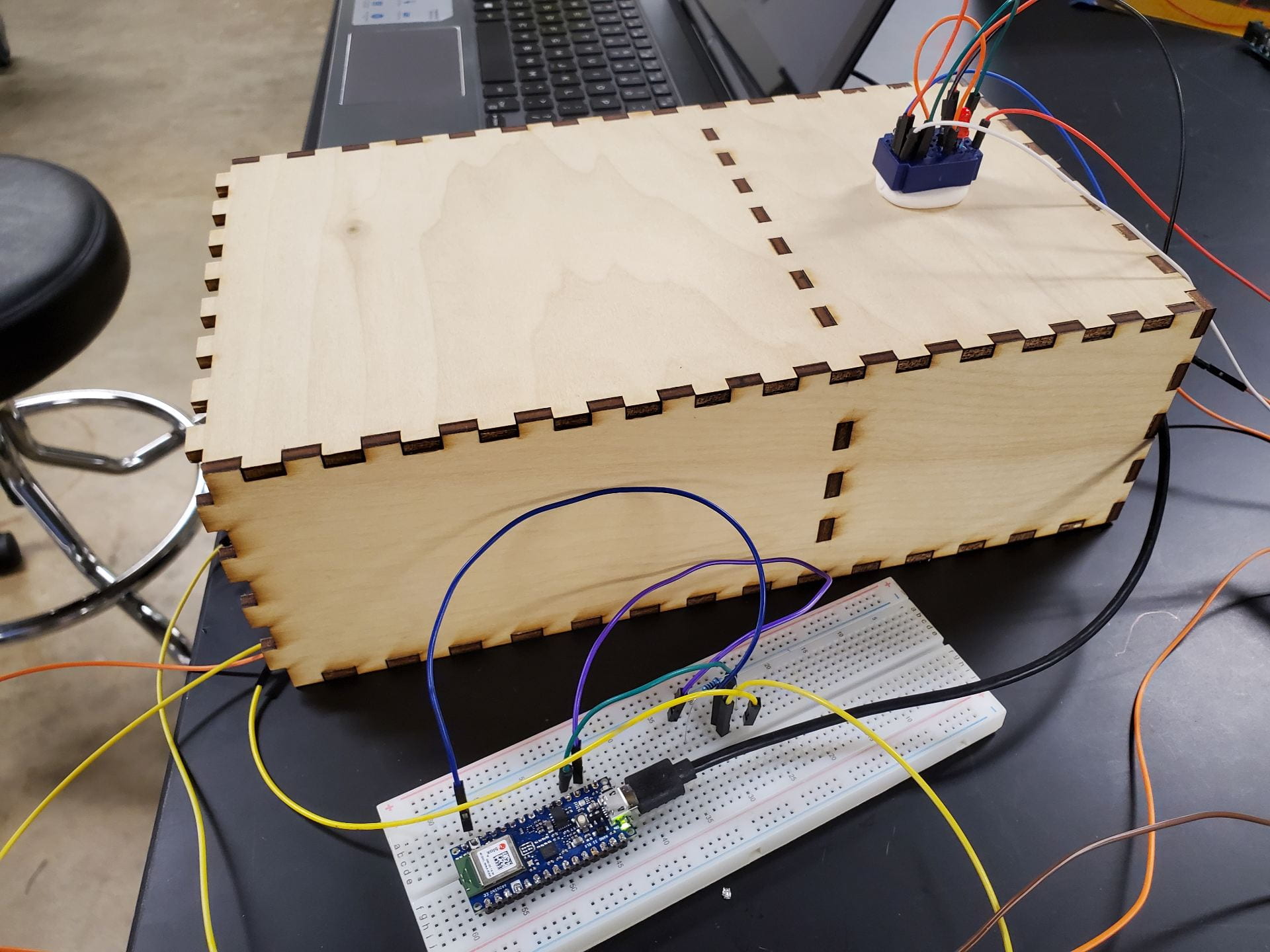
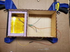
One side is heavily insulated with polyiso (what the pink box is made of), and the other holds the batteries. There’s a small hole in the middle to lead the wires from the battery to the heating pad. This design improves upon our pink box because it solves a problem that’s been plaguing us for a while: what exactly to do about the battery. Previously, our options were to have the battery externally connected – which exposes it to environmental dangers and also makes the device unwieldy to carry – or have the battery in the same space as the heating chamber – which exposes it to heat hot enough to decrease its lifespan.  The two-chamber design means that everything is internal, but the battery is kept near ambient temperature.

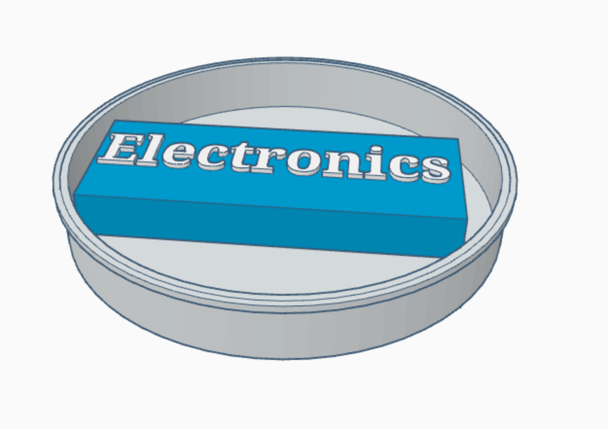
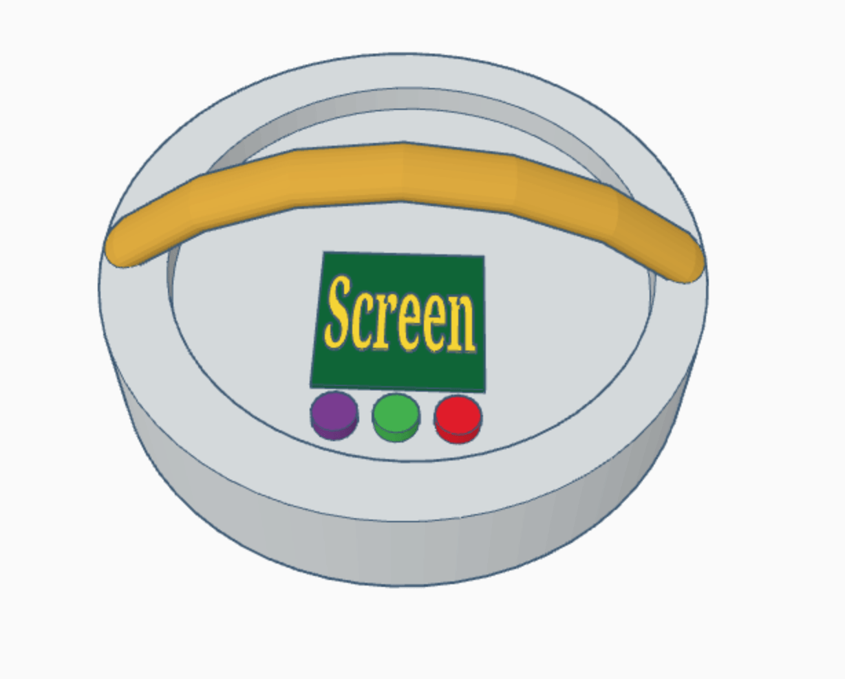
As of writing this blog post, we are currently in the middle of performing heat tests on our new two-chambered device. We also have some other big improvements in the works, including an interactive mockup of the UI, a tentative vertical model of the two-chamber box, and of course, the long-awaited completion of the breadboard. Thank you readers for following Team Petri-FI on our design journey, and cross your fingers for good news next week about that darned breadboard.

Week 3: Stretching Our Imagination (& Silicones)

*Content warning: My project deals with pediatric sexual abuse. Please exercise self-care while reading.

When Elise, Shannon, Alex and I demonstrated our low-fidelity “flip”, “twist”, and “swivel” models to our client over Zoom, we got some feedback that led us to consider aspects of our model we hadn’t, by any stretch of the imagination, thought about before. Sure, easy rotation like that of the “flip” model could be helpful, but what if nurses needed to be able to perform pelvic examinations regardless of whether they were sitting down or standing up? What if you had the (very probable) scenario of a child not positioning themselves at the most correct angle for the supine or prone orientations, and they were slightly tilted one way or the other? Our model needed to simulate the real pelvic exam experience.

This made the “swivel” model the clear winner – it was the only model that could freely rotate the labia and hymen to various angles above the horizontal. Still, our client pointed out that we’d need some sort of mechanism to lock the rod in various orientations, so it wouldn’t slip or swing when nurses interacted with the labia.

medium-fidelity swivel model w/ Dragon Skin labia!

We decided to make a slightly higher-fidelity prototype of our swiveling model (especially since the low-fidelity one collapsed mid-Zoom meeting…), and attach a Dragon Skin 10M labia model we constructed using the scaled-down LUCIA labia mold we 3d-printed last week.

It actually worked quite well! The main challenge we ran into, however, was that the weight was imbalanced, so the model would only hang at the correct angle in the prone position. So we knew we would need to brainstorm and prototype some rotation lock options in Week 4. We’re currently thinking about adding grooves to the ends of the rod and a notch to the holes in the frame, so the user can simply set the rod into the notch at the desired orientation.

And, given the fact that we had to nail the labia into the cylinder in the model… we’d need to brainstorm better attachment methods of the labia/hymen to the base, so that different labia and hymen varieties can be easily interchanged during practice pelvic examinations.

So we went (somewhat) back to the drawing board on attachment methods. Should we use a screw-on cap? Well, that would be secure, but it might be hard to always twist it on in the right orientation. How about a snap-on cap? Well, that might still rotate after snapping on. Buttons? A bayonet mount? An embroidery hoop? We’ve definitely been stretching our imaginations on how to attach things to the base.

And meanwhile, we’ve also been stretching something else – silicones! We finally began testing materials for the labia and hymen this past week, and the results have actually been quite surprising. Since the LUCIA project uses Dragon Skin for their labia, we were expecting Dragon Skin to work the best for our project… but what we realized was that because our model requires nurses to separate the labia with their fingers, it needs to better mimic the elasticity of human skin. What we found was that a different silicone rubber, called Ecoflex 30, seems to be the most promising in terms of elasticity. However, as user feedback is incredibly important for a training model, we are working to get input from local pediatric gynecologists on our sample labia models.

Platsil silicone labia w/ attached silly-putty hymen
Dragon Skin 10M labia & hymen
Ecoflex 10, Ecoflex 30, & Dragon Skin 10M samples curing


This coming week, now that we have a functional model frame and labia mold, we’ll be focusing a lot on improving our hymen and labia prototypes, creating prototypes with more materials, and constructing attachment and rotation lock mechanisms. One thing we did realize, as you might be able to tell in the Dragon Skin labia picture above, is that it’s difficult to grip the labia and separate them, since there’s so little surface area on the side. Our client gave us that same feedback during our prototype demonstration. So this week, we’ll also focus on altering the CAD design of the labia mold to incorporate more surface area on either side of the labia to better facilitate labial traction.

Team PIPER after our midsummer presentation! 🙂

Overall, this week we dove headfirst into prototyping and the nitty-gritty of mixing and curing silicones, building frames, and working in CAD. But the mid-summer presentations at the end of the week made me take a huge step back and look again at the broader context of what we’re doing and why. I am genuinely so glad that our team has the opportunity to hopefully make such a significant impact on the quality and accessibility of clinical evaluations of pediatric sexual abuse and assault, and that we have such a wonderful support system at Rice 360 and the Texas Medical Center, full of people invested in helping our project succeed and encouraging us as people, friends, and colleagues. I can’t wait to see what these next couple of weeks bring.

-Shivani


Week 3: Full Speed Ahead!

Content warning: My project deals with pediatric sexual abuse. Please take care of yourself and feel free to forgo reading any parts of this blog. 


Now for the fun part- prototyping! My team began this week by creating low-fidelity prototypes of the five bases that resulted from our screening and scoring matrices. We quickly ruled out two of the five, as we felt that they were not as effective and efficient as the other three options. That left us with three base options: flip, swivel, and twist. All three were viable options and worked equally well, so we chose to consult our client. She indicated that she liked the swivel option best, leading us to pursue this base and rotation mechanism.

Left: Flip; Center: Swivel; Right: Twist

The swivel solution is a u-shaped base with a dowel rod running through it. A cylinder is permanently attached to the dowel rod. Different labia and hymen caps can then be screwed onto the cylinder. The model rotates by simply spinning the dowel and turning the base 180 degrees. Additionally, we plan to incorporate a notch system that will allow the model to lock into the supine and prone positions, as well as a variety of different angles to accommodate nurse position (sitting or standing, different heights, etc.). After our client indicated her satisfaction with the swivel base, we created a more medium-fidelity model of the solution that is sturdier and won’t fall apart when touched like our precarious low-fidelity model. 

Medium-Fidelity Prototype of the Swivel Base

Concurrently, our team worked on modeling the labia and hymen. For the labia, we acquired the CAD files from LUCIA, allowing us to scale down their mold and use it to create our labia. We 3D printed the scaled down mold, then used silicone rubber to cast the labia. Satisfied with the detail and appearance of the mold, we began testing other materials to find the one that most nearly mimics skin in texture, elasticity, and appearance. Smooth-On is a company that manufactures many different synthetic skin products, and we were able to test different varieties of Dragon Skin and Ecoflex. As of now, we think Ecoflex 30 is the best skin alternative, but we have ordered a few more materials to try. Additionally, we are meeting with a gynecologist next week to get her opinion on which skin would be best to incorporate into our model.

Left: LUCIA labia mold and silicone rubber labia; Right: Materials testing of Dragon Skin and Ecoflex

As far as the hymen goes, we have two options. Option one is to extend the LUCIA labia mold so the vaginal opening is covered with a thin layer of synthetic skin material. We could then simply cut the hymen out of the extra material. We did test this method with some of our synthetic skin samples, and our client indicated that the hymen did move correctly when performing labial traction. However, another key aspect of the model is that the hymen falls due to gravity when rotated from supine to prone, and we are not sure if this method could accomplish that movement. Option two is to create the hymen separately from the labia and attach the two using some kind of silicone adhesive. We have created some low-fidelity hymen using slime and silly putty, and we will continue exploring this option as we begin to finalize our materials.  

Left: Option one- cut hymen out of excess material; Right: Option two- create hymen separately from labia

On Thursday, Dr. Wettergreen, a Rice engineering professor with extensive design experience, stopped by to provide feedback on our design in the form of a prototype evaluation. Dr. Wettergreen was complimentary of our work, and he gave us numerous suggestions for enhancement. He recommended using an embroidery hoop to secure the labia and hymen and a bayonet mount to attach the two to the base. He also advised that we utilize a commercially available notch system to lock the dowel in place rather than trying to reinvent the wheel. This prompted our team to look into options like gears for the notching system. Overall, we are grateful for his feedback and ideas for further design iteration.

Friday marked the halfway point of this internship! They say time flies when you’re having fun, and that has held true so far! We were able to celebrate our accomplishments thus far with midsummer presentations, where we got to share our work with our colleagues. It was wonderful to see all the amazing work my peers are doing, and I enjoyed getting to share what Team PIPER has accomplished. I am proud of how far we have come and excited to see how far we will go. 

Team pictures after our midsummer presentation!

Outside of work, the wonderful TAs created a campus-wide scavenger hunt for us! On Thursday, we had a yummy meal of Torchy’s Tacos, and then the hunt was on! It was a blast, despite the scorching Texas sun! My team ran over two miles around campus, searching for clues. I’ve realized I’m very competitive, as I was in it to win it. In the end, we tied for first place! Everyone was rewarded with Tiff’s Treats, and I loved my snickerdoodle cookie. 

Scavenger Hunt Team 4 Pictures with Shivani and Kaitlyn!

Since we are at the halfway mark, I wanted to offer a bit of self-reflection. This internship has taught me that I am very much an external processor. I think out loud, especially when it comes to design. This can be both a blessing and a curse- a blessing because it allows my team to build off my ideas and a curse because a lot of my ideas are half-baked, which can lead to some confusion. Additionally, I have found myself getting attached to certain ideas. For example, I favored the swivel base over the other two options, and I would’ve been sad if our client chose otherwise. This realization will help me be more self-aware and open-minded in the future. Thus far, this internship has taught me so much about myself, and I can’t wait to see what the next three weeks have in store!


See y’all soon,

Shannon


P.S.- If you made it this far, I applaud you! These posts keep getting longer and longer, but I have so much to share about my amazing experience!

Week 3: Project Pivots

I think that one thing that can be challenging for me in the design process is keeping myself from getting overly attached to certain ideas – it’s easy for me to get excited about one solution that I think will work best. While my enthusiasm for promising designs can be a good thing, it also makes it harder to consider other options and perspectives. However, during this internship, I’m learning that keeping myself open to making (potentially large) changes throughout the designing and prototyping process is extremely important. This is especially true given our particular project, which is designed to be used in a setting very different from my own, and which is very dependent on user feedback. Although something may seem like it would work very well based on my own background and context, it may not be nearly as effective or efficient in other settings. In addition, by becoming too attached to one design , I am potentially missing the opportunity to create an even better final product, either by adapting that new idea or by combining it with my own.

I initially came to this realization as my team was moving through our prototyping stage. After we had prototyped our two initial ideas, our team was very excited about the feasibility of our designs. We then, based on feedback from our international clients, began to work on performing exposure calculations in order to ensure that the various configurations of masks and UV bulbs which we were considering would actually supply the necessary dosages (approx. 1 J/cm2) to all of the masks on each mask-holding frame. In addition, we wanted to make sure that there were no huge disparities between the dosage received at different parts of each frame, as this could lead to some masks being insufficiently disinfected and others being overdosed (which can lead to degradation).

In order to do these exposure calculations, we created a spreadsheet, using the different grid-rectangles to represent points on a mask-hanging frame. Then, we used a formula into which we input bulb power, bulb length, bulb distance from the frame, and exposure time, and then received a dosage value for each point on the frame. This spreadsheet was color-coded to represent the dosage received. 


We performed these calculations initially on our simple square mask-holding frame for the box prototype. By varying the height of the bulb in regards to the frame and adjusting the exposure time, we were able to achieve very promising results. We were particularly excited about the fact that we estimated we would be able to disinfect 1.2 masks per minute (our initial goal was 0.2). However, we thought that they could still be better, leading to the development of “Gertrude,” our third prototype. Gertrude, while larger than our original square mask frame, can fit two rows of about 6 masks. In addition, two bulbs would be suspended above and below this frame (one above/below each mask row). With this configuration, we were able to achieve even more uniform and reliable dosage in a shorter time – our masks per minute rate was 2.88!


Now, here is where my earlier self-reflection becomes applicable. After performing these calculations, I was very excited about the concept of moving forward with the square box idea, particularly with the new, double-row frame; it seemed to work mathematically, and appeared very easy to use. However, on Thursday, we had a prototyping workshop in which we were given the extremely strong advice by an expert to move forward with our cylindrical oil-drum concept (with a different internal frame) and disregard the box design due to the much higher accessibility and standardization potential of oil drums. This was very hard for me to accept initially, as we were essentially being told to take a number of steps back and return to brainstorming potential solutions which would be applicable with the oil drum. After discussing this feedback with one of our clients, we found that she also agreed, solidifying our future path. Over the next several days, we worked to come up with several new, promising solutions, and I quickly began to move past my frustration and back into a state of excitement. Although making such a big pivot was challenging, I have now realized it will also allow us to make an even better solution. Though at first it felt like much of what we’d done up until our redesign had been a waste of time, through reflection I have realized that all of our previous work led us to this point, and will help us to make even more informed decisions in the future. 

Moving forward, our team will continue to prototype our new oil-drum frame ideas, as well as perform exposure calculations on them to determine their feasibility and effectiveness. By the end of this week, we hope to have a set design which we can move forward into higher-fidelity prototyping.

Outside of project work, we also did some fun intern activities this week! We had a group scavenger hunt around campus (my team tied for first place!) which was a great way to bond both with some of my teammates and with other interns. In addition, after our mid-summer presentations on Friday, we took some cute team photos!

Week 3: Foil. Lots and lots of foil.

My favorite part of being a small child was not recess, not naptime, but crafts. My mom and I would sit together every afternoon for “pony drawing time,” and once I was introduced to pipe cleaners, it was decided: I was a hardcore crafter. From Lincoln Log cabins to knitted monsters to intricate Hexbug race tracks, I loved to create things. 

It’s sad that so many people lose touch with their crafty side once they hit third or fourth grade. Although I continued to draw as a hobby (especially dragons and flames), the pom poms, popsicle sticks, and even pipe cleaners disappeared into the storage closet. Who knew that it would be the Rice 360˚ internship that brought me to craft once again?

Early this week, we began the exciting process of low-fidelity prototyping. Dubbed “lo-fi” prototyping, this process involves creating very simple physical representations of the ideas that we brainstormed last week. When I discovered that the tray overflowing with straws, balloons, foam, and even treasure–yes, treasure!–was the toolkit for our prototypes, I was thrilled. After beginning with a time-constrained egg drop challenge early on Monday morning (I’ve attached the picture of our balloon-cushioned, cotton ball-insulated, cup-enclosed design below), we got right to work on creating our lo-fi prototypes. 

After evaluating our brainstormed ideas, we had settled on two possible geometries for our device: a cylindrical shape with a removable frame that slides out vertically, and a rectangular box with removable trays that slides out horizontally. To determine which shape was more user-friendly and efficient (in terms of maximizing masks sterilized per unit time), we decided to create lo-fi models of both. 

Carl (seen below) was our first prototype. As you can see, we used about ⅔ of a roll of aluminum foil to create the circular mask frames and supports for the overall framework. The masks would be stretched between hooks attached to the sides of the ring, as well as a suspended hook-imbedded piece in the center (made of many criss-crossing pipe cleaners). UV light bulbs (represented by the blue paper rolls) would be attached above and below the diameter of the mask ring in alternating orientations. The whole frame would come in and out through its suspension from the lid of the cylinder by fishing wire.

Our second iteration was affectionately named Geraldine (below). This was the rectangular idea, featuring sliding trays (made of bamboo rods connected by corners made of pipe cleaners with ~many~ layers of foil and tape for stabilization) over which the masks would be hooked. We used a random cardboard box we found lying around the OEDK to represent the box size; however, we discovered that the dimensions were a bit awkward since it was too wide to comfortably hang masks the entire length across but too short to make two layers. 

Thus Gertrude (pictured below) was born (created?) as a way for us to determine the optimal dimensions for the mask frames. We extended both sides and attached a rod down the middle so that two rows of masks could be hooked up. With 64 cm by 64 cm dimensions, we were able to fit 12+ masks per tray, which suggested a very high sterilization efficiency, especially if more than one tray was used per device.

Throughout this process, I learned why we always start with low-fidelity prototypes instead of jumping straight into realistic designs. We had to do a lot of crumpling, squishing, bending, and taping of our foil-based framework, and because of this material flexibility, we could adjust our dimensions and even shape quite easily. The craft supplies that allowed me to create fun creatures as a child allowed us to visualize and interact with our abstract brainstormed ideas, and through this process, we rapidly learned the pros and cons of each device shape. (Don’t worry–you’ll hear all about Carl, Geraldine, and Gertrude’s skills and struggles in a later post!)

As a whole, I vastly enjoyed lo-fi prototyping. Not only did the prototypes give us a concrete idea of the device designs we were considering and allow us to convey these ideas to others in a simple (and aesthetically entertaining) manner, but we got to use craft supplies to do so! This week was instrumental to developing and choosing our design…and stay tuned, because ***spoiler alert***: Carl may be getting a younger sibling sometime soon 🙂

Week 2 Reflections

Week 2 brought a lot more clarity to our project, as this was the week we were able to connect with potential users here at Rice EMS. We were able to set up a meeting with them and talk to a few EMTs on campus to gain more information about our problem, as we were having difficulty understanding it in context. After connecting with REMS we had a clearer picture of what problem we were trying to solve, and they were able to handle our device and give us a lot of useful advice and features that they would have liked to see. This gave us some direction for our brainstorming which we started doing towards the end of the week. We found that breaking down our problem into a few components was a lot more productive to brainstorm then full solutions, at least at that point in the process.

We also began to split up the tasks of the project into 4 main groups: Electrical, Coding, CADing, and Human Factors. I was the lead on the electrical aspect of the project, and for me that meant that I would be taking the current circuit and moving it from a bread board to a perfboard to increase the stability of the previous teams prototype. I am looking forward to next week because I have always been fascinated by Electrical work, and so this was a good time for me to learn some new skills related to that field. It sounds like it may be difficult, but I also find that difficulty is part of the charm of learning new skills, so I am ready for what week 3 throws at me!

Week 2: Thinking About the Global Water Crisis

It’s hard to believe that we are almost to the halfway point of this summer program! While we have made great progress in our project as you can read about in my teammate Kenton Roberts’ blog post for week 2, I spent a lot of time over these past few weeks reflecting on my project’s problem space: the global water crisis. 

Globally, 844 million people don’t have access to usable water. Access to clean water is a crucial stepping stone for development. Without it, people are not able to practice proper hygiene and sanitation. Children get sick and are less likely to go to school. Parents worry about and tend to water-borne illness and struggle to make a living. This past fall semester, I had the opportunity to take the course BIOE365: Sustainable Water Purification for the Developing World. One of the first things we learned in the class was how the term “developing world” is misleading and often reductive to the countries which are included. It groups countries as a whole into a category of low social and economic metrics. However, oftentimes crises we relate to “developing countries” are crises which are occurring in the daily lives of the vulnerable people in the US: communities of color, low-income people residing in rural areas, tribal communities and others. 

For example, the water crisis is often a problem we don’t consider to be one in our own state or even in our country. However, in Cochran, Texas for example, families must haul water by car or foot or purchase trucked water at high costs. Families in this city use only 50 to 100 gallons of water per month for whole households of up to 8 people while the average American uses 88 gallons of water per day. It is estimated that 2 million Americans still don’t have access to clean drinking water and more than 44,000,000 million Americans are served by water systems which violate the Environmental Protection Agency’s Safe Drinking Water Act. Overall, I just wanted to bring attention to the fact that sometimes in the global health space we neglect the vulnerable populations in our own communities and distance ourselves from global issues by getting stuck in the mindset that these issues only happen thousands of miles away across country borders and oceans. 

Throughout my experience being involved with Rice 360 these past 3 years, I learned about how to effectively design for communities with limited resources.  Reading about how we need to be careful of the verbiage we use and the mindset we sometimes take on in the global health field has played a key role in my own approach to the engineering design process and inspired a shift in the role I want to play as a physician working in the global health space. 

Rice 360 blog

Blog number one through three-week review 

My reflection for the past few weeks was learning more about the rice 360 program. I also was able to learn about the interesting projects and was assigned to work with the Texas Heart Institute to develop a heart-lung model for a new wireless pacemaker. I was assigned a team and we went to the medical center to meet clients and learned more about our project. We also meet many interesting guest speakers and learned a lot about the engineering design process. Our team also conducted low fidelity prototypes and plan on creating high fidelity prototypes in the coming weeks.

Week 2 Reflections

Hello again everyone! 

This past week has definitely been a week of twists and turns for our team that really showed the value of getting consistent feedback from your clients. Ending out the week, we had determined and defined our design criteria (cost, ease of set-up, ease of maintenance, durability, and accuracy of motion), as well as completed our first round of brainstorming for each of our four device components:

  • The heart motion
  • The lung motion
  • The tissue attachment mechanism
  • The motor and Arduino housing component
  • The exterior-interior connection

However, during our client meeting on Friday with the Texas Heart Institute (THI) team, we found that many of the solutions and mechanisms that we had brainstormed were not fully aligned with some of the design constraints. Namely, the fact that the tissue could not be impaired in any manner following our device’s use. We had previously made the assumption that the tissue could be punctured in order to attach it to the ’tissue’ table. This assumption proved problematic due to the fact that following the tissue interfacing with our device, it will need to undergo further analysis that would be negatively impacted if there were any holes or tears in the tissue. As a result of this newfound constraint, we headed back to the drawing board. It was fortunate that this concern was found before any significant prototyping had been done, and we still had a lot of time.

In this round of brainstorming, we made some alterations to the component designations for which we were brainstorming. For example, due to the highly integrated nature of the heart and lung motion, we decided to define and brainstorm these mechanisms as one component. We also got rid of the connection between the exterior and interior components in brainstorming, as the feasibility of each was heavily dependent on the heart and lung motion chosen. 

Following our second round of brainstorming, we performed a morphology chart of the brainstormed components to create several holistic solutions. We subsequently narrowed down these holistic solutions to two final solutions using a Pugh Scoring Matrix. We then sketched out and built a low fidelity model of each of these solutions to get a better idea of what each would entail and possible future challenges. 


Solution 1: Our tissue table (table on which the tissue will be clamped) is built on an axle that has a string running through both ends of the platform that will facilitate a rocking (heart) motion. This axle is constructed then onto a second platform that is attached to a set of tracks. When pulled by a string, these tracks will assist in mimicking vertical (lung) motion. 


Solution 2: The tissue table (table on which the tissue will be clamped) is a small platform that is located on top of a triangle. This table has strings attached at each end that would facilitate a rocking (heart) motion when pulled. The mechanism here is similar to that seen in a seesaw. Meanwhile, the middle platform is attached to the stationary table by a pole that is running through the center with strings being used again to this time create a vertical (lung) motion.


*Note: The vertical motion seeks to mimic the heart’s motion that is caused by the lung. 


Moving forward into next week, we plan to develop a higher fidelity version of each prototype and perform some additional iterations. Based on the findings of our low fidelity prototype, it seems that it might end up being best to combine the best aspects of each solution into one final one. Additionally, we plan to use SolidWorks to 3D print some of our components, write Arduino code in a manner that allows for independent control of the heart and lung motion, and hopefully bring our device to life!

Signing off,

Kaitlyn

Week 2.5: Smoke and CAD

Intro

Over the past week and a half, the program really got going. We are now almost halfway through the internship, and it has gone by so fast. After the initial process of finding our footing with the previous prototypes, we sort of split into two parallel segments, one of which involved continuing with the Minicubator prototype’s code and circuit, while the other focused on starting our own design process and figuring out what we want our final device to accomplish.

Continuation of Minicubator’s Path:

For a while, I was mostly focused on the circuit. Initially, I got the PCB that Minicubator left us to operate, so the OLED lit up and we were able to program incubation periods. The heating pad never heated up, however, and when I tried to re-wire the battery towards the heating pad, the PCB started smoking in three different places. So I tried to unsolder several of the components, including the OLED and the transistor, and rebuild the circuit on a breadboard where I could manipulate it more.

PCB before shorting out:                                PCB after shorting out:


Breadboard version:

I also made a digital version so that if anything got unplugged by accident (which happens frequently with breadboards) we would have a model to use to fix it:

This follows the schematic of the PCB that we were given, but because of an issue with the circuit design (essentially there are currently two separate circuits that need to be run in parallel on the same battery, but it sort of seems like it was set up to run with two batteries, which is not really an option), it doesn’t quite work. On the bright side, though, we finally fixed all the issues with compiling the code, so the software is now uploaded to the new microcontroller (which was a different version than what Minicubator used)!

Our Own Design Path:

The other main thing we did this week was go through our own design process, starting from scratch instead of using other teams’ prototypes. We broke our problem into six design blocks and brainstormed enough ideas to take up two whiteboards. Then, we scored these partial ideas to narrow them down and morphed them into a few complete designs. The two main options are a thermos system and a lunchbox system. The thermos system would more effectively retain heat, thereby requiring less power, but it is messier in terms of wiring and user interface. The lunchbox would require more power, but would be much neater. Below are some rough CAD models of each design.

Lunchbox:

This is the basic setup of the inside, including the tray with the petrifilms on top of a heating pad in the middle, with the battery and electronics housing on either side. The wires from the electronic housing go through the hinge to the back of the display screen and the buttons. The SD card is easily accessible on the underside of the lid.

This shows what the lid will look like. When it is closed, there will be a handle on top to carry it easily, and the screen and buttons will be conveniently located in the upper righthand corner.

Thermos:

Here you can see the inside of the main heating chamber of the thermos. On the bottom, there is a heating pad underneath the tray with the petrifilms. There is also a small thermistor, shown in purple below. Then, all the wires (orange) connect to a plug (black) which has to be plugged in when the lid is put on. The battery (black) is attached to the outside via a cam strap (darker gray).

This is the tray that houses the electronics. If we continue with this idea, we will most likely attach the tray to the top of the thermos, so that the user does not have to interact with all the wires, aside from the ones that plug into the heating chamber below and into the battery on the outside. The only problem with this is that the user would need to detach the tray to access the SD card, which is on the underside of the OLED (see next image).

The top of the thermos has a handle to use to carry it, and the same screen and button setup as the lunchbox. We would need to use a drill press to create holes in the metal for the buttons and screen, and for the cable coming from the battery (not shown).

This is what the thermos would look like fully assembled.

Future

Later this week, we have our mid-summer presentation, where we will show the rest of the program what we have done so far. Tomorrow we plan to use Pugh scoring to decide on a final design to pursue. We are also going to perform a heat loss experiment on a thermos and a lunchbox to help us make an informed decision. We have made so much progress in the past week and a half, and I am so excited to keep working on this design!