Intro
Over the past week and a half, the program really got going. We are now almost halfway through the internship, and it has gone by so fast. After the initial process of finding our footing with the previous prototypes, we sort of split into two parallel segments, one of which involved continuing with the Minicubator prototype’s code and circuit, while the other focused on starting our own design process and figuring out what we want our final device to accomplish.
Continuation of Minicubator’s Path:
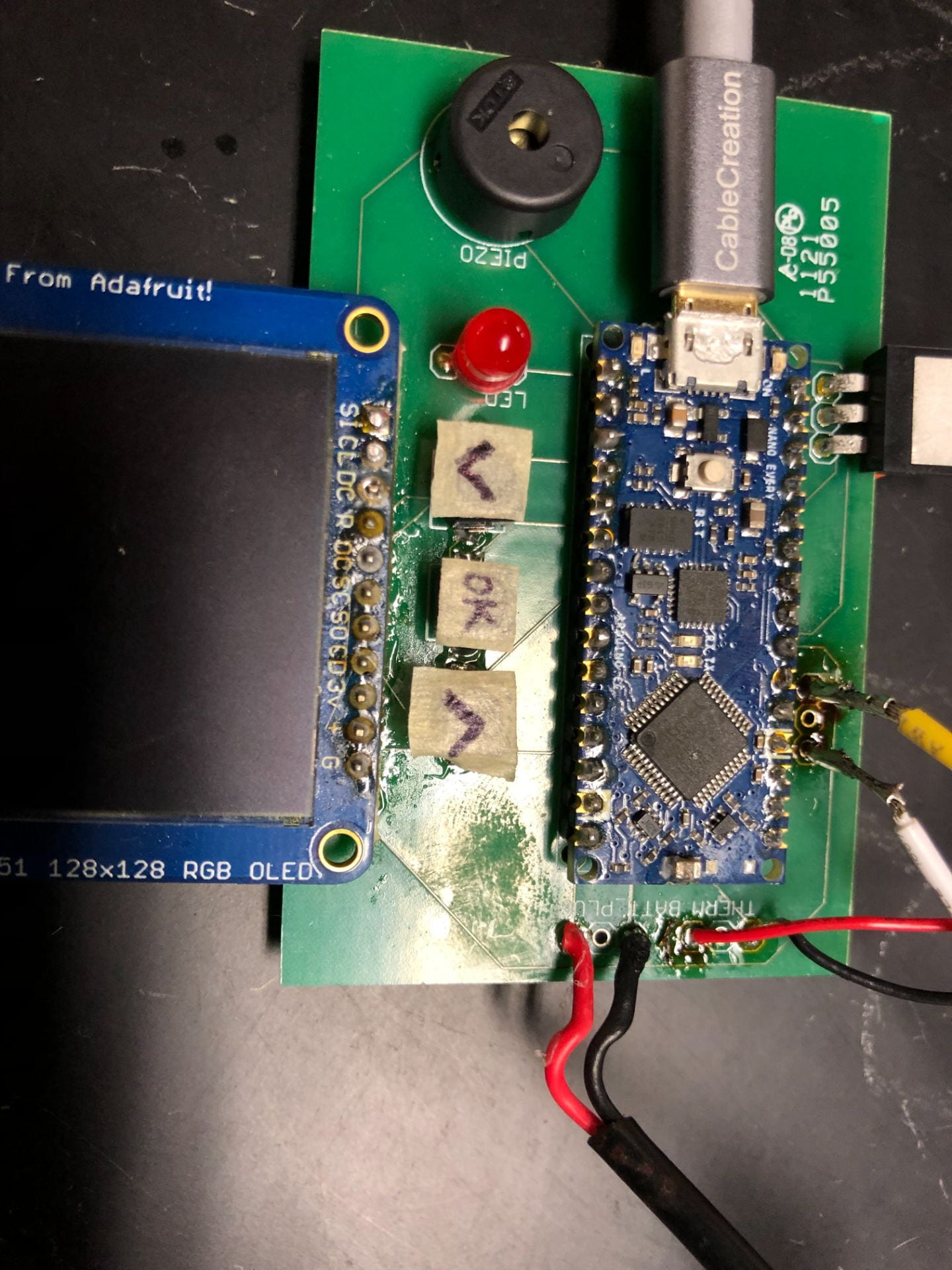
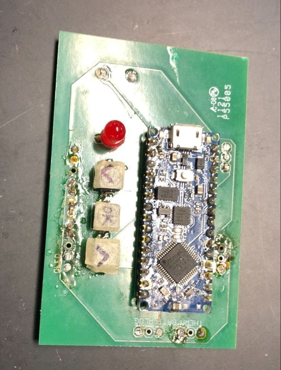
For a while, I was mostly focused on the circuit. Initially, I got the PCB that Minicubator left us to operate, so the OLED lit up and we were able to program incubation periods. The heating pad never heated up, however, and when I tried to re-wire the battery towards the heating pad, the PCB started smoking in three different places. So I tried to unsolder several of the components, including the OLED and the transistor, and rebuild the circuit on a breadboard where I could manipulate it more.
PCB before shorting out: PCB after shorting out:
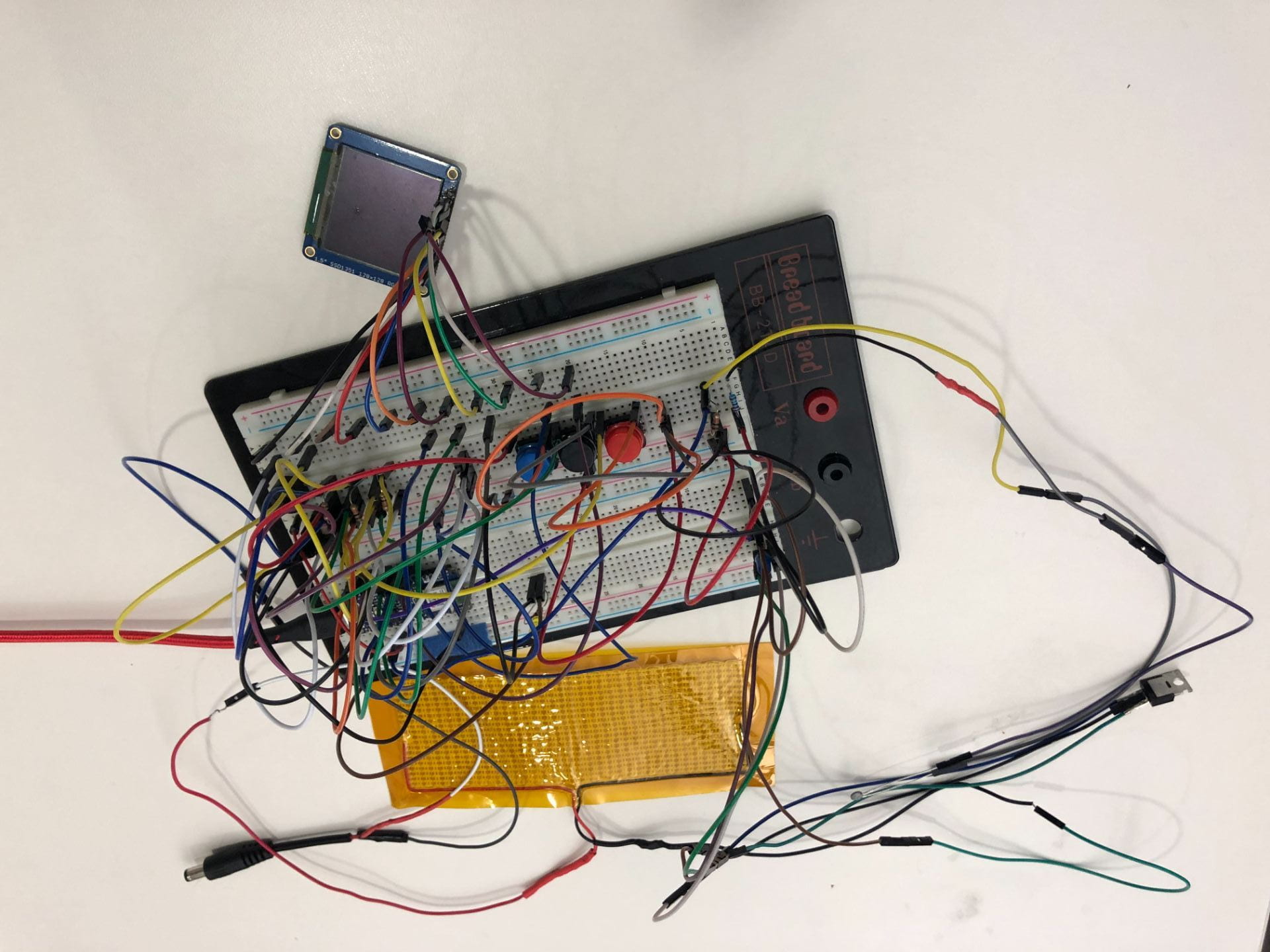
Breadboard version:
I also made a digital version so that if anything got unplugged by accident (which happens frequently with breadboards) we would have a model to use to fix it:
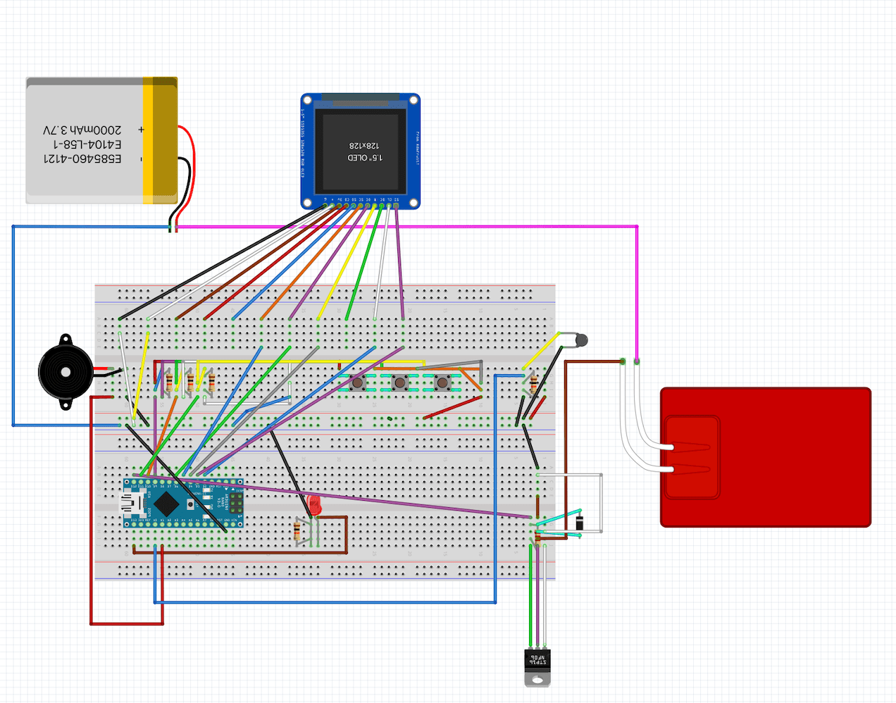
This follows the schematic of the PCB that we were given, but because of an issue with the circuit design (essentially there are currently two separate circuits that need to be run in parallel on the same battery, but it sort of seems like it was set up to run with two batteries, which is not really an option), it doesn’t quite work. On the bright side, though, we finally fixed all the issues with compiling the code, so the software is now uploaded to the new microcontroller (which was a different version than what Minicubator used)!
Our Own Design Path:
The other main thing we did this week was go through our own design process, starting from scratch instead of using other teams’ prototypes. We broke our problem into six design blocks and brainstormed enough ideas to take up two whiteboards. Then, we scored these partial ideas to narrow them down and morphed them into a few complete designs. The two main options are a thermos system and a lunchbox system. The thermos system would more effectively retain heat, thereby requiring less power, but it is messier in terms of wiring and user interface. The lunchbox would require more power, but would be much neater. Below are some rough CAD models of each design.
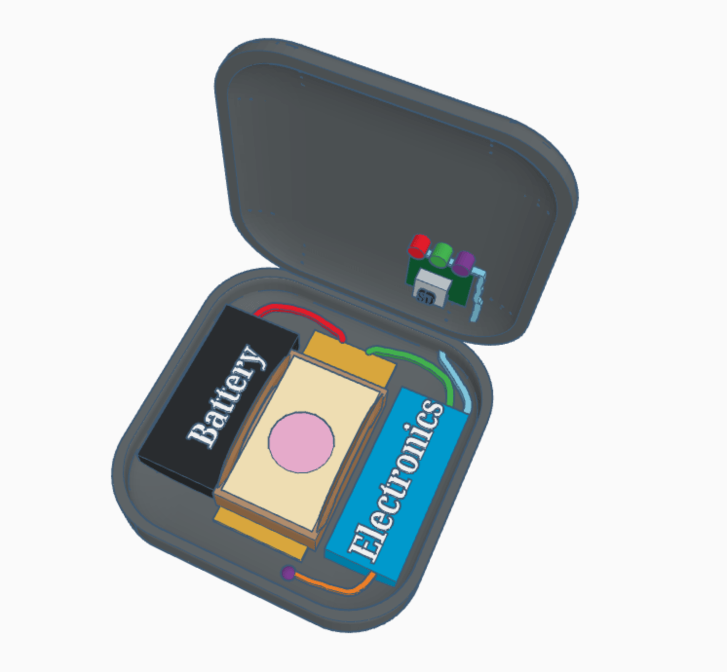
Lunchbox:
This is the basic setup of the inside, including the tray with the petrifilms on top of a heating pad in the middle, with the battery and electronics housing on either side. The wires from the electronic housing go through the hinge to the back of the display screen and the buttons. The SD card is easily accessible on the underside of the lid.
This shows what the lid will look like. When it is closed, there will be a handle on top to carry it easily, and the screen and buttons will be conveniently located in the upper righthand corner. 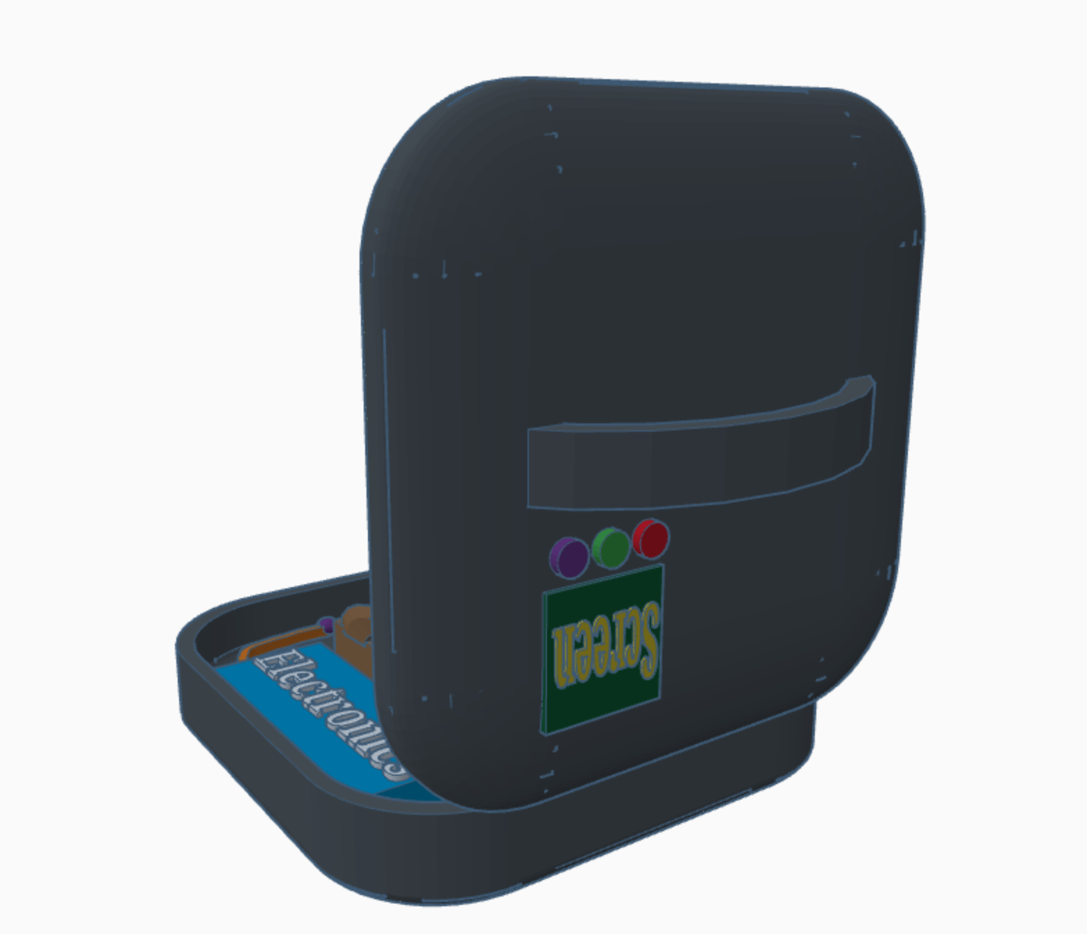
Thermos:
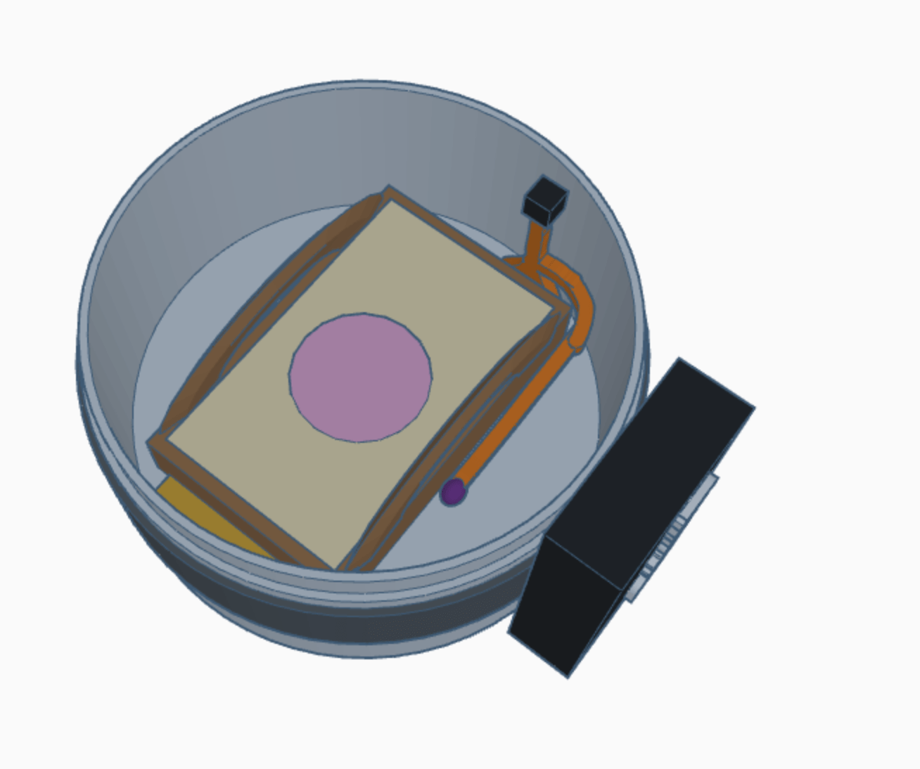
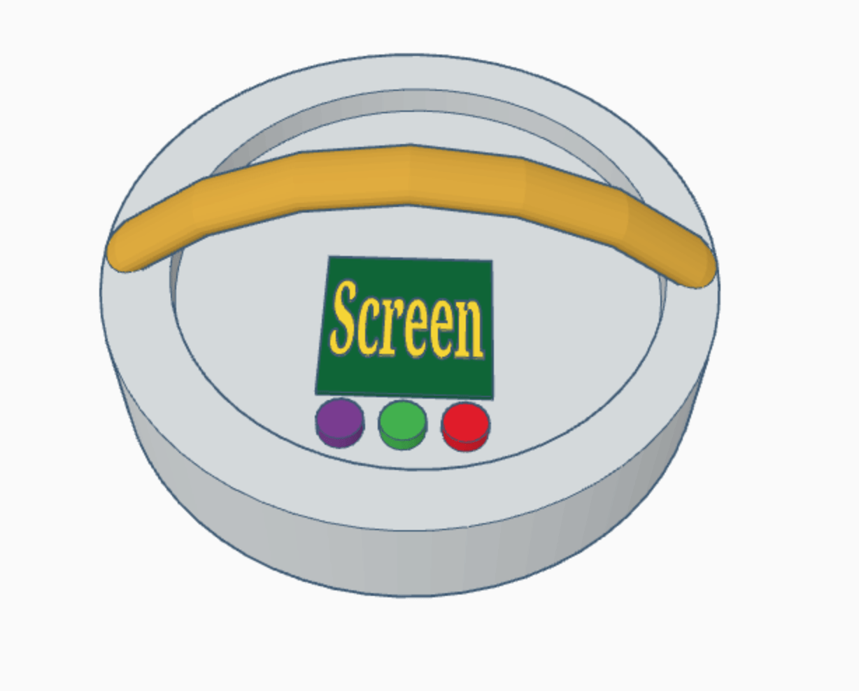
Here you can see the inside of the main heating chamber of the thermos. On the bottom, there is a heating pad underneath the tray with the petrifilms. There is also a small thermistor, shown in purple below. Then, all the wires (orange) connect to a plug (black) which has to be plugged in when the lid is put on. The battery (black) is attached to the outside via a cam strap (darker gray).
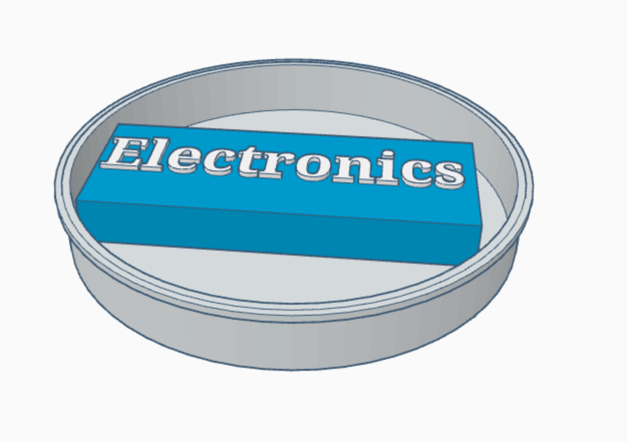
This is the tray that houses the electronics. If we continue with this idea, we will most likely attach the tray to the top of the thermos, so that the user does not have to interact with all the wires, aside from the ones that plug into the heating chamber below and into the battery on the outside. The only problem with this is that the user would need to detach the tray to access the SD card, which is on the underside of the OLED (see next image).
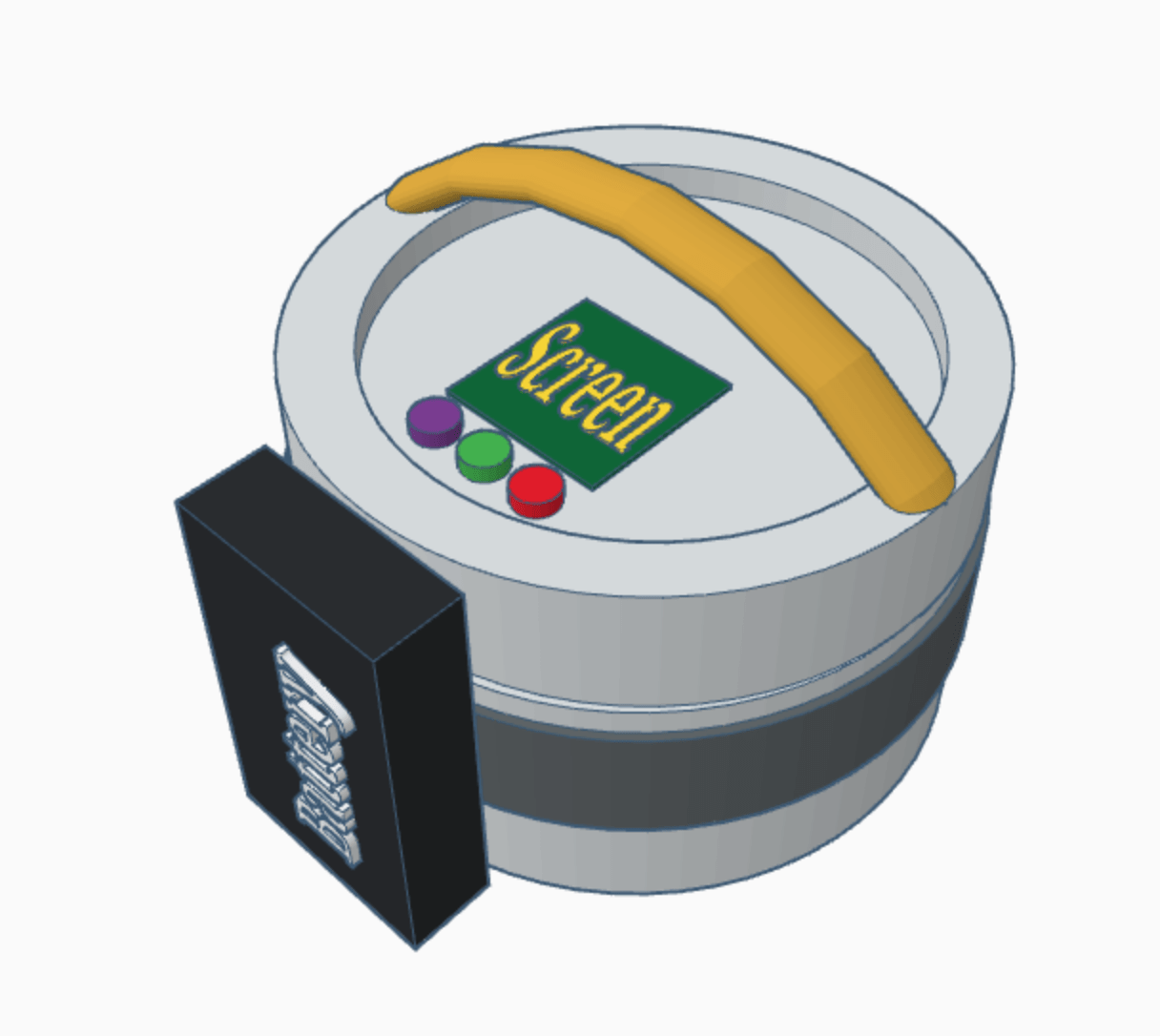
The top of the thermos has a handle to use to carry it, and the same screen and button setup as the lunchbox. We would need to use a drill press to create holes in the metal for the buttons and screen, and for the cable coming from the battery (not shown).
This is what the thermos would look like fully assembled.
Future
Later this week, we have our mid-summer presentation, where we will show the rest of the program what we have done so far. Tomorrow we plan to use Pugh scoring to decide on a final design to pursue. We are also going to perform a heat loss experiment on a thermos and a lunchbox to help us make an informed decision. We have made so much progress in the past week and a half, and I am so excited to keep working on this design!