Forearm Rotation: The Wrist Twisters in Action

It’s hard to believe that 3 weeks of SEED are already over; we’re almost halfway done with the internship! The thought brings mixed feelings to my mind.

For one, this means that the international students from Malawi and Brazil who I have become good friends will be leaving soon. I’m certainly going to miss them afterwards but I’m we’ll stay in touch. And of course, that only means that we’ll make the most out of the remaining month.

I’m also starting to realize that we only have 4 weeks left to finish prototyping and working on our project. Although our progress is good, the thought is still surprising and motivates me to maintain our team’s momentum and finish strong. This was the first full week where we worked on the forearm rotation device and prototyping is coming along well.

Our team decided to take a modified approach to the engineering design process. Conventionally, the design team will brainstorm ideas, screen/score them, and then start prototyping their main design solution. However, our team instead brainstormed ideas and jumped straight to low-medium fidelity rapid prototyping. With the help of 3D printing, we can easily fabricate our ideas. Once we have functional prototypes for all of our brainstormed ideas, we plan on revisiting the scoring process and using physical testing to base our decisions. This route was suggested by Dr. Wettergreen and is more suitable since we are working off an old design and our brainstormed modifications are too minute to be easily screened using the conventional method.

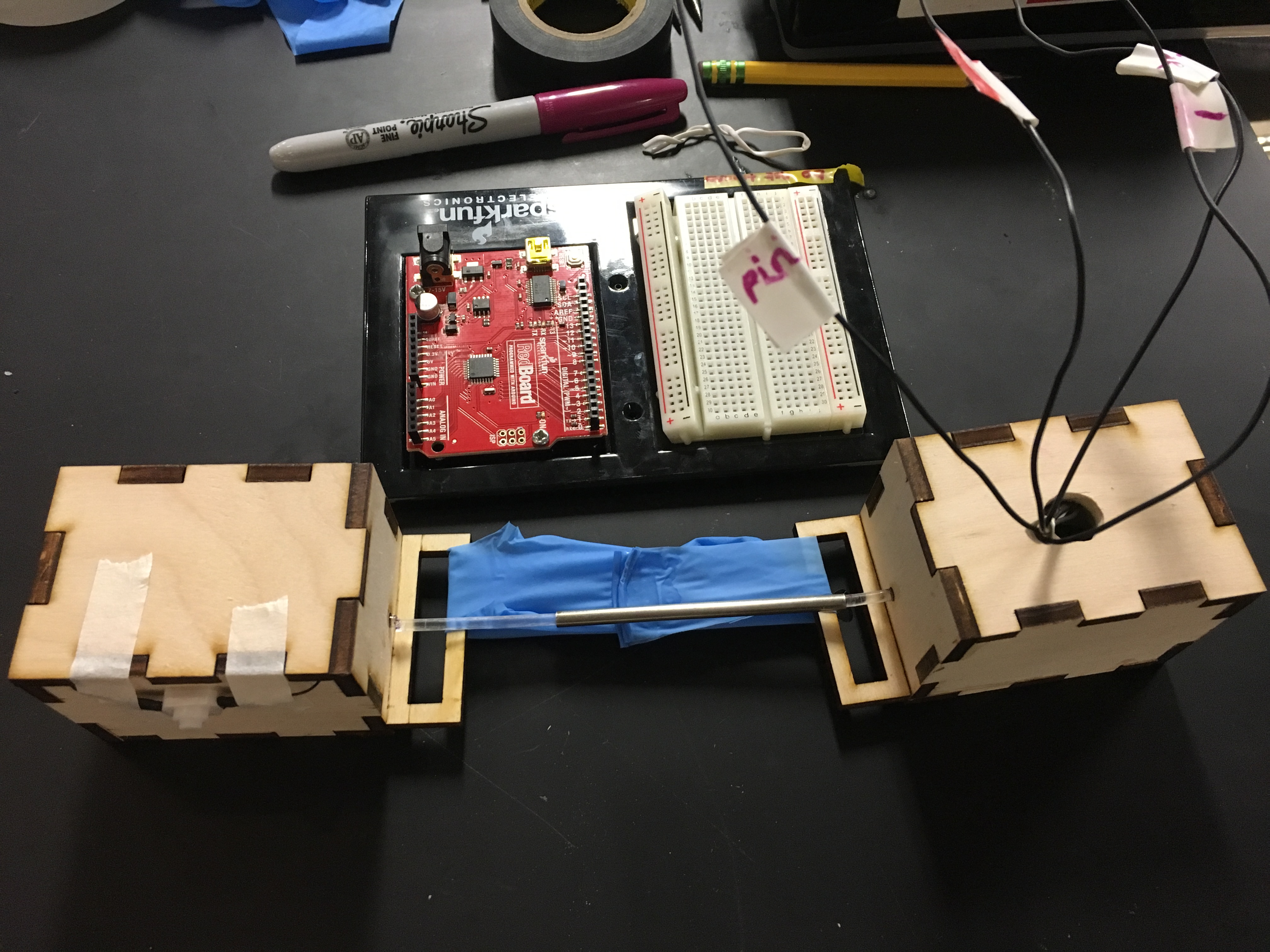
The 3D printer allowed us to easily recreate the old team’s prototype, shown here.

IMG_6909

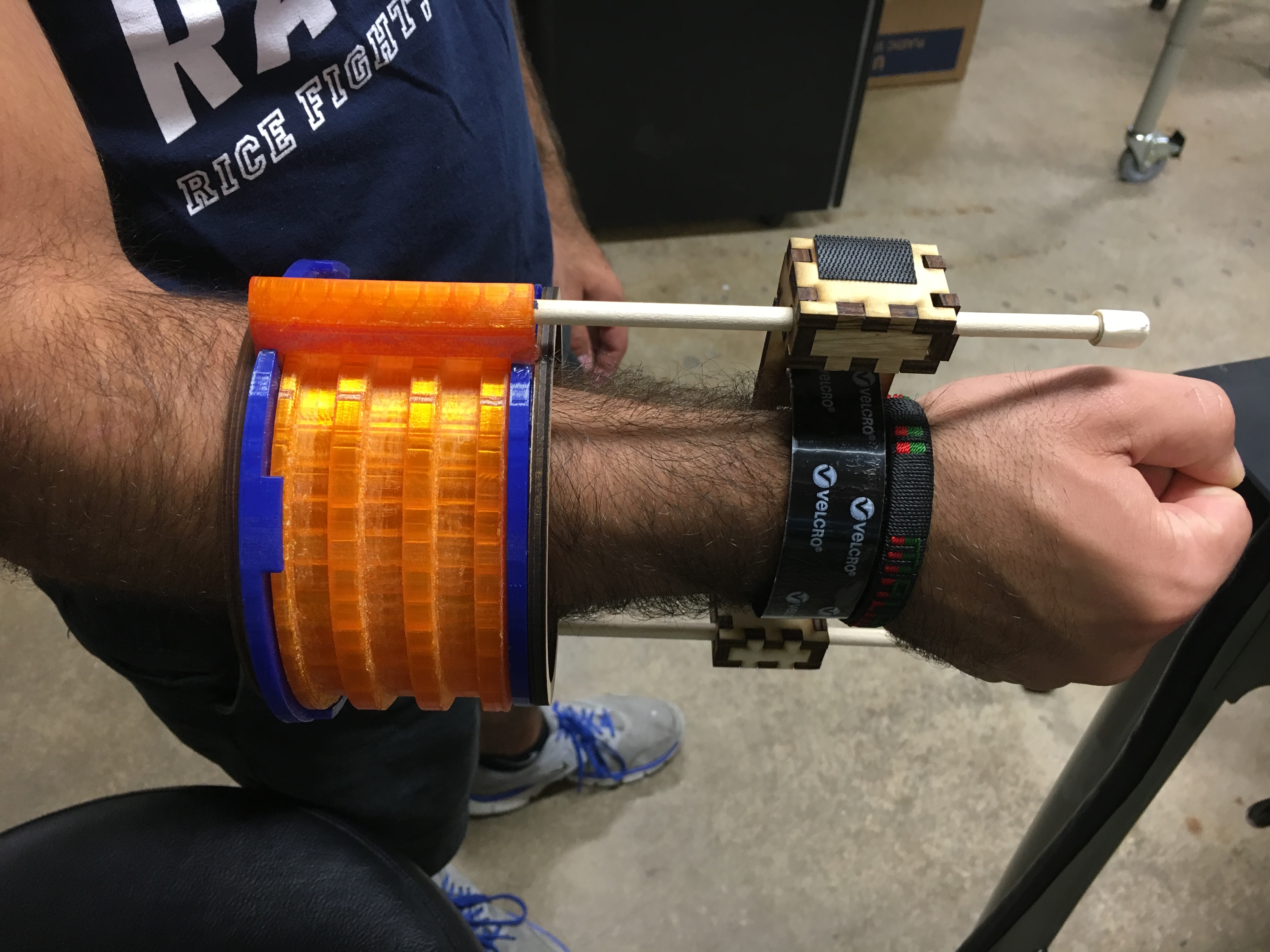
After the brainstorming and initial screening process, we have found 3 main ideas we want to work with. An exterior tab sliding on rails, and interior tab sliding within rails, and concentric rings sliding on an inner tube. Each one of these ideas maintains the original team’s shell for measuring forearm rotation but modifies the geometry of the technique. Our goal is to reliably reduce friction in this design block, while also maintaining an accurate and durable device.

Next week, we will put together our ring design ideas, test/score them, and finally pick one design to move forward with. This will allow us to move on to the wrist and elbow attachment mechanisms, our other two design blocks.

Week 3 of the Rice 360° Experience

I can’t emphasize enough how much real world experience helps to put years of learning and coursework from classes into perspective. Last week, I found and ordered switches that I would need to construct the mode selection part of the Incubaby UI. This week, I researched several different circuits to integrate a rotary switch and implemented the most promising one. By trial and error, I was finally able to see the voltage changes between each position on the switch, which supported the calculations I had done beforehand. Then, I devised a sketch in Arduino that takes these voltage measurements and associates them with the mode that the incubator needs to be in; the Arduino then switches over to the part in the code that runs the specified mode of the incubator. And there’s some of ELEC coming together to make some sense!

Coming into this week, I expected the Incubaby UI to be a reformatted version of the current front panel. However, it turned out to be a complete redesign of the front panel. It should account for different situations that would arise when the incubator is in use, including the notorious one in which the doctor/nurse doesn’t put the temperature sensor on the baby (Note: the incubator adjusts its temperature based on the baby’s temperature). It was overwhelming but interesting to see how devices are not always used in the way in which they were meant to be used. Additionally, we need to make sure that doctors/nurses can easily tell how well the baby is maintaining its temperature in the incubator. For this, we might use multicolor LEDs (another first for me) to inform the nurse/doctor if the baby is too cold (blue), too warm (red), or normal (green). The device should also remind the user to put the strap on the baby and alert if the strap is incorrectly placed on the baby. And we need to do all of this, while making sure that the doctors/nurses are not confused/intimidated by too many lights/alarms going off. The brainstorming for this UI was definitely very involved. Just when we thought we had covered all of the necessary components, we come up with handy things like “door open” alarms and sensor straps hanging from telephone wires. 

I learned how to effectively use a matrix to decide when indicator lights should be on/off, what colors they need to be, what alarms need to go off, and what alarms take priority over others.

matrix

As you can probably tell, I need to work on making it a bit more coherent.

Alongside that, I’m having a lot of fun sketching up some different designs for the front panel!

Hopefully, this upcoming week, I can get my thoughts together and discuss the plan with the rest of team. I can’t wait to see how the UI comes together! Maybe, first see what the front panel looks like and then, awhile later, see how the lights and alarms work out!

#Wrist_Twisters on the Going

This week we worked full time on our forearm rotation device project and occasionally we participated on a couple of workshops. We built a replica of the Rad Torquies final prototype from CAD files they developed using SolidWorks. Below is a picture of a measuring ring with wrist a attachment that we built using the Rad Torquies CAD files. The problem with the model was that the tabs were sliding in the grooves with much friction as they get pushed by rotating the wrist attachment. Our goal was to try and eliminate the friction and enhance accuracy of the device whilst maintaining the design objectives.

We built three different models of the measuring ring in trying to address the shortcomings. Basically we altered geometry and size of the rings and tabs and in two of the models we tried employing addition materials. Solidworks and 3D prinnter were our buddies over the course of the week. We developed our own CAD files and 3D printed each iteration in the prototypes. Our three prototype models were named after their geometric structure and these were concentric circles model, inner tab model and outer tab model. The inner and outer tab models are like inverted versions of each other. During testing, we observed that there was friction-less surface between tabs and respective rails because they were 3D printed using similar material as such this resulted in free motion of the tabs which was undesirable. This prompted that we should attach a thinner sheet of foam on the tabs’ sliding surface to introduce some friction and it worked pretty well. We also explored widening size of the tabs inorder to enhance stability when sliding along the rails. Below are pictures of the three models.

In addition, I undertook two workshops on laser cutting with Mikaela and post-processing with Dr Wettergreen. Mikaela taught us how to develop files for laser cutting using Adobe Illustrator and how to use the laser cutter. As part of practice I laser-cut a box out of ply wood to house an audio sensor circuit developed by my workshop partner, Lucas. He developed the circuit in a similar workshop which he and other SEED interns were attending with Helen. We wrapped up the week with post-processing workshop where Dr Wettergreen taught us procedures for fine tuning our final design before commissioning. We learnt surface smoothing and coating methods. It was a great experience and am looking forward to learn lots of stuff during the summer.

THIRD WEEK


Zicky

Hello world, am enjoying my stay in USA, Texas, Houston and most especially at Rice University .My third week at Rice University has been successful and wonderful, I have learnt a lot of things. I have learnt how to use software’s like adobe Illustrator and Engrave Lab, which are used in Engineering design. In addition I have learnt how to operate two laser cutter machines; Epilog Fusion M2 40 and Boss LS-3650, this helped me to engrave and cut whatever I designed on the two software’s without any problem. During this second week we also hand a PCB work shop were we learnt soldering process and how to use arduinos. The picture below shows some of the items that I have made using Laser cutter machines.


final Bugatti 1O1

WEEK #3 – WORKSHOPS AND FIRST WEEK OF CERVICAL CANCER PROJECT

CERVICAL CANCER PROJECT

This has been an awesome week working hand in hand with Karen and Mary on our project. so much has been done during the week, and loved the way thing have been lining up for the project.

just a brief description of the project, me and my team we are working towards developing a part of a cervical cancer screening model which is the cervix in four different stages of cancer, with the purpose of using it in the low resource areas to train health care practitioners in cervical cancer screening procedure. the main focus of the project is to demonstrate the color change of the cervix when its swabbed with acetic acid in the actual Visual Inspection with Acetic Acid (VIA) procedure and also make sure that the design is of low cost as possible suitable for these low resource areas.

On Monday we had the chance of visiting one of our clients working place at the LBJ Hospital with the aim to observe the VIA or any other related procedures and have a clear picture of how the actual cervix look like, so my team members went into the operation rooms with different patients being treated. prior to the visit me and my team members organised our goals  for the visit, all went as planned except for the part that we also wanted to check out any existing models like ZOE model. the visit went well for us and it was really a learning experience on how to handle clients visits.

For the project we are also working with Emillie who is like our client and partner, and had a meeting with her on Wednesday which went well and exciting that we are on the same page in this project and she was really amazed with our progress in the research and the solution options we have developed so far.

so in general for our project this week we managed to do;

  1. Research on cervical cancer causes, signs, symptom, screening and treatment
  2. Research on existing screening methods basically PAP smear and VIA
  3. Client visit and meetings
  4. Developing Design criterion
  5. Pairwise Comparison chart
  6. Brainstorming for possible solutions
  7. Morph Charts for the design Blocks
  8. Screening the Design solution options

We have finally got a design solutions for the project The 3D painted Cervix with Heat Sensitive Paint for color change. So far we have started ordering materials to start Prototyping our first low fidelity prototype.

WORKSHOP

Now here is the exciting part of the week, doing some relaxing and very educative work, on Tuesday learnt using the Adobe Illustrate to design 3D objects, thanks to Mikaela our TA for making it easy to learn the package in a very short period of time and i managed to design a Housing for the Sound Sensitive Lamp that my workshop team mate Mary made herself.

IMG_2307

The whole thing was really fun and finally getting to use the laser Cuter for the Housing it was Awesome!!!!!!

The second part of the Workshop was with Dr Wettergreen, we did the Surface Modification and Finishing were we learnt how to use different finishing tools both manual and powered tools. The workshop was great and we had to do all the activities that Dr Wettergreen pointed out like filing, using the Dremel and splay painting.

IMG_2300

Engineering!!

After meeting with our client, Sonia Parra, we learned more about our project. The goal  of our project is to make a model cervix that can change colors to indicate the presence of cervical cancer. My team has spent a lot of time this week researching cervical cancer. We spent hours looking at pictures of different stages and symptoms of cervical cancer. We even went to a clinic where we got to see a cervical exam in person. We also began looking into different color changing mechanisms that exist. After researching, we met with our client’s undergraduate assistant, Emilie, to confirm that we were on the right track. Using the information that we compiled, we were able to establish design criteria and begin brainstorming. We came up with many ideas that we narrowed down using morph charts, screening matrices, and scoring matrices. We are now prepared to begin prototyping and looking into different materials for our cervical models. So far, we have used air dry clay for our low fidelity prototypes.

This week we also paired up to make lamps in Arduino and laser cutting workshops. I was able to use adobe illustrator to design a cute box. Then I used my design to laser cut a box out of wood.  Meanwhile, Borgestein was working on the sound sensitive led light. Afterwards we were able to put our work together to create a lamp. I look forward to continuing to use the laser cutter and the 3d printers more often!

82a348ec-2172-4a35-bcf8-124d43db0c46b71407d1-629b-44b3-b058-2765b53d3cb5

Week 3 #much in progress#

hello all,

This week has been very wonderful, I remember how i mentioned and briefly explained on Team Toco’s ( Lucas, Zach , Nathalie and myself) New project.

IMG_2297

Team Toco

From the proof of concept which doctor Carns explained to us we were most likely to base our solutions around the specified materials and that is what we did. This week we continued with research , then we  set our design criteria, brain stormed  and moved on to Pugh Scoring Matrices where we ended up with three solutions which are a bit similar but maintained them so that we test the solutions. All the processes  we went through stated above were for the attachment of the Tocodynamometer.  We started out with the attachment first because we thought it wise to do so.On Wednesday we  came up with the attachment part of the our  prototype.Which consists of two lazer cut boxes, which now holds the electronic components. The boxes are attached to each other through the latex glove which is the only stretchy material we have for now since our orders are  not yet in. We worked on the electronics part of the project as well.We used arduino to come up with the Circuit and the display of the light intensity values.We had workshop for arduino basics, soldering ,electronics (group 1) and lazer cutting(group 2) that was  on Tuesday .We were put in teams of two one in group one and the other in the second group.I was paired up with Allie, so i soldered a sound sensitive light

IMG-20160624-WA0002

and Allie made a a lazer cut box for it.So from the workshop we had we used that knowledge on our group to come up with the circuit for our fairly medium fidelity prototype. So the box on the left consists of an LED which is powered up with a 9 volt battery  and has a switch taped outside the box. On the right is a soldered circuit consisting of a photo resistor which will change in resistance depending on the amount of light it receives as the elastic stretches due to contractions.The wires protruding out of the box are connected to the arduino for display of the values of light levels through the code we came up with. Below is the picture of the prototype!!

IMG_6345

So far the tocodynamometer prototype  is able to pick up any movement of the belly which includes breathing . So we will be  working on a code which will separate the two, display the values in form of a graph, duration of one contraction etc, and should have an alarm when the three conditions below happen;

>5 contractions in 10 minutes

One contraction >120 secs

<60 second intervals

We will work on its accuracy, so there is a lot to come. Earlier today we continued with our workshop we started on Tuesday, learnt about tools, using the right ones always for each job, reading instructions before using anything.We learnt how to spray paint. Furnish wood etc.

 I also remembered today we were introduced to a minor project . It is about a device that is to measure the temperature of newly born babies which are susceptible to hypothermia.The device has three LED s each depending on the color can tell if a child is cold , OK or hot.Our scope is to do with  the user interface and aesthetics. We all had a meeting with the client. #nice weekend to all of you#


week three

this week have been working on our cervical cancer model with my team mates Waheed and Karen.
we did some research on the problem and visited LBJ hospital where we hard to watch how the remove the biopsy from the cervix son that the cervix we are to design should match the actual cervix.
our project is moving on so well and our clients Sonia is giving us all the information that we need to know in order to be able to meet our clients needs. so far we have done all the design process  which includes brainstorming, morph chats, pairwise comparison chats and scoring matrix  in which we have come up with  our final solution in which we are going to make a 3d print heat sensitive cancer model which is going to change color to white when it is subjected the minimum temperature that we are going to set. and we have started building our low fidelity prototype.

i have also built some circuits on Arduino boards and have done  soldering of the sound sensitive lump shown below. the lumps (LED’s) lights up upon hearing a voice or noise

IMG-20160624-WA0002

finally we have also done some wood works, learning materials which we need to use in order to make the wood smooth. the materials includes sand paper and files  and have learned how to apply vanish on the board and how to use spray paints

IMG_2301

the whole week has just been so awesome and have gained a lot of experience and am expecting lots of things this coming week.

Third week: Optoco is lit!

Week three: June 24, 2016

Lucas Gutembergue da Costa


During this week I spent most of my time working with team Toco, which is composed by me, Nathalie, Zach and Chimwemwe. Our goal is to create a low-cost tocodynamometer that will be used in developing countries. A tocodynamometer is a device used to detect and measure uterine contractions of a pregnant woman during labor.

We started with a proof of concept developed by Dr. Carns (shown below). It consists of two pieces of fiber optic cable that touch each other covered by hypotube. The two pieces of fiber optic cable are attached to fabric and there is an LED in one end of the fiber optic and a photoresistor on the other end. The fabric ends are attached to the woman’s belly and as the belly stretches because of the contractions the fiber optic cables separate causing the amount of light going through the cables to decrease. This decrease is detected by the photoresistor therefore we know that a contraction has happened.

 IMG_6292 IMG_6294

Fig 1 and 2 – Low fidelity prototype of the Optoco made by Dr. Carns

We started by doing research on the background of our problem, the different devices currently in the marker to monitor uterine contractions, regulations and patents. Then we defined our design criteria and design constraints, brainstormed solutions and selected the best solution using a scoring matrix.

Then we made a medium fidelity prototype based on Dr. Carns idea to evaluate the sensitivity of the device, i.e. how much the voltage reading from the photoresistor changes as the device is displaced. The prototype was made by laser cutting wood boxes to hold the LED and the photoresistor, with the same assembly of fiber optic cable and hypotube in the middle. The circuit is powered by the Arduino and the voltage reading is recorded by the Arduino too. The preliminary results of the device’s sensitivity are very optimistic.

IMG_6345

Fig 3 – Medium fidelity prototype

The next steps for the Optoco are to process the data we receive from the photoresistor and output the data the doctors and nurses want. This will involve creating an algorithm to process the information.

SEED Week 3

Third week of SEED is just wrapping up, and Team Toco is already making good progress on our design. We spent Monday doing more research, then moved on to define the design criteria for our project. In the afternoon, we started brainstorming possible solutions — to start off with, we mainly focused on getting the mechanical portion of the device to work so we can reliably send light through the fiber optic and measure it at the other end when we pull the wires apart. After doing our brainstorming, we ran our ideas through a Pugh matrix to help us sort out what to move forward with. We ended up with three possible solutions that we’re pursuing simultaneously for now. All of them involve housing the electronics of our device inside small plastic boxes and running the fiber optic between the boxes, which we’ll eventually 3D print. The major differences between our ideas involve what kind of elastic material will run between the two boxes: right now we’re thinking of using either sewing elastic, rubber strips, or a rubbery accordion-style material. We’ve ordered supplies for all of those, and we’ll start testing each of them out on Monday when they arrive.

In the meantime, we’ve finished up a medium fidelity prototype of the design, using laser cut wooden boxes to house the electronics. For right now, we’ve got the LED attached to a 3V battery and taped to the fiber optic cable in one box, and a photoresistor and a small circuit hooked up to an Arduino kit in the other box (see the picture below). We can get light coming through the fiber optic really well with this setup, and we’re able to record it on the Arduino and see the changes in light level based on how far we pull the boxes apart. Now we’re working with our Arduino kits to learn some more code — we’re all going to take our kits home this weekend and try to get more comfortable working with them. We plan on starting to write some real code next week, starting off with trying to get the computer to just recognize when a contraction is occurring, and eventually working up to plotting the number and duration of contractions on some kind of display, and triggering an alarm when one of our three “danger” conditions is met.

IMG_6345

Apart from working on the Optoco, we also spent some time this week learning to use a bunch of tools at the OEDK . We had a laser cutting workshop where we got to design our own lamps and laser cut them out of wood. Part of mine is pictured below — we should be staining/painting them next week sometime!

photo 1 (1)